100%
FI-122
EFI SYSTEM — Electronic Control System
7M-GE
ECU
Voltmeter
E1
7M-GTE
ECU
Voltmeter
E1
E2
B
F02789
F02811
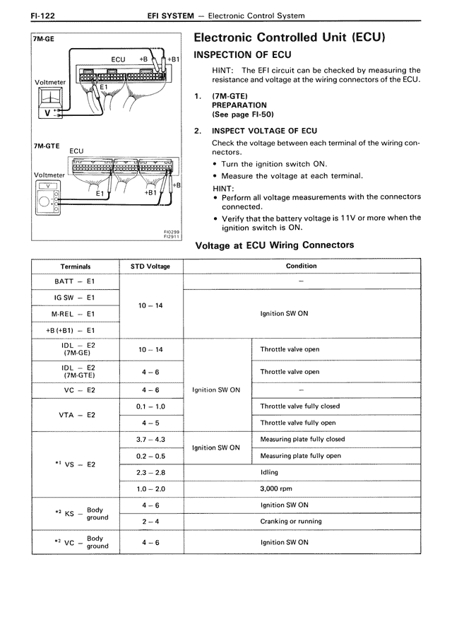
Electronic Controlled Unit (ECU)
INSPECTION OF ECU
HINT: The EFI circuit can be checked by measuring the resistance and voltage at the wiring connectors of the ECU.
1. (7M-GTE)
PREPARATION
(See page FI-50)
2. INSPECT VOLTAGE OF ECU
Check the voltage between each terminal of the wiring connectors.
• Turn the ignition switch ON.
• Measure the voltage at each terminal.
HINT:
• Perform all voltage measurements with the connectors connected.
• Verify that the battery voltage is 11V or more when the ignition switch is ON.
Voltage at ECU Wiring Connectors
Terminals | STD Voltage | Condition
BATT — E1 | — | —
IG SW — E1 | 10 — 14 | Ignition SW ON
M-REL — E1 | 10 — 14 | Ignition SW ON
+B (+B1) — E1 | — | —
IDL — E2 (7M-GE) | 10 — 14 | Throttle valve open
IDL — E2 (7M-GTE) | 4 — 6 | Throttle valve open
VC — E2 | 4 — 6 | Ignition SW ON | —
VTA — E2 | 0.1 — 1.0 | — | Throttle valve fully closed
| 4 — 5 | — | Throttle valve fully open
*1 VS — E2 | 3.7 — 4.3 | Ignition SW ON | Measuring plate fully closed
| 0.2 — 0.5 | | Measuring plate fully open
| 2.3 — 2.8 | | Idling
| 1.0 — 2.0 | | 3,000 rpm
*2 KS — Body ground | 4 — 6 | | Ignition SW ON
| 2 — 4 | | Cranking or running
*2 VC — Body ground | 4 — 6 | | Ignition SW ON