100%
FL-124
EFI SYSTEM — Electronic Control System
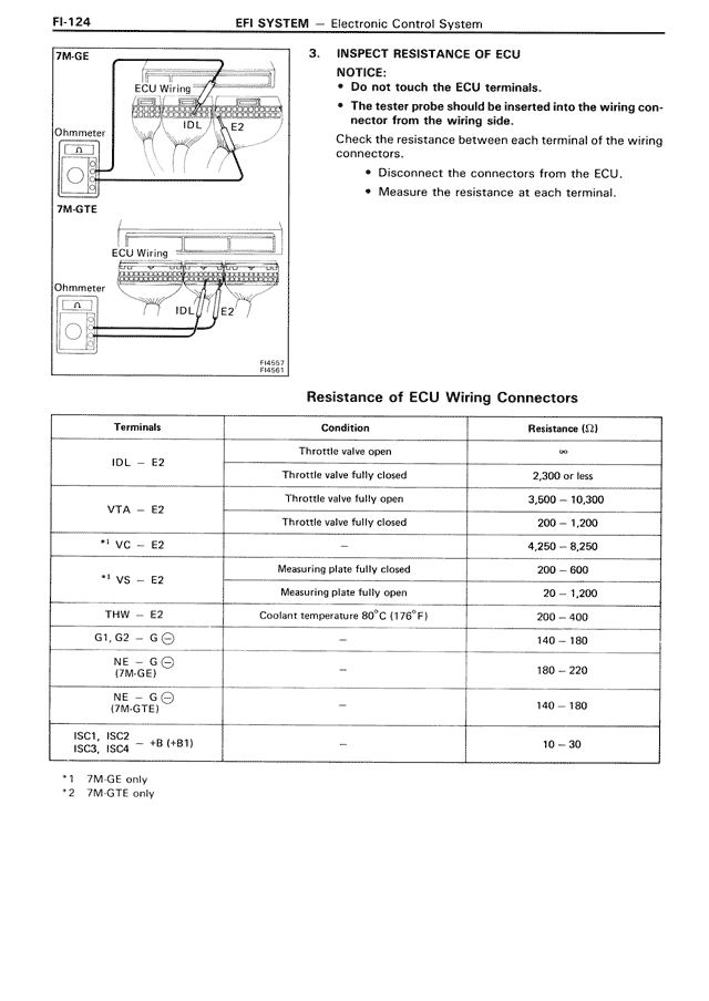
7M-GE
[DIAGRAM showing ECU Wiring with IDL and E2 connections to Ohmmeter]
7M-GTE
[DIAGRAM showing ECU Wiring with IDL and E2 connections to Ohmmeter]
F04221
F01251
3. INSPECT RESISTANCE OF ECU
NOTICE:
• Do not touch the ECU terminals.
• The tester probe should be inserted into the wiring connector from the wiring side.
Check the resistance between each terminal of the wiring connectors.
• Disconnect the connectors from the ECU.
• Measure the resistance at each terminal.
Resistance of ECU Wiring Connectors
Terminals | Condition | Resistance (Ω)
IDL - E2 | Throttle valve open | ∞
IDL - E2 | Throttle valve fully closed | 2,300 or less
VTA - E2 | Throttle valve fully open | 3,600 — 10,300
VTA - E2 | Throttle valve fully closed | 200 — 1,000
*1 VC - E2 | — | 4,250 — 8,250
*1 VS - E2 | Measuring plate fully closed | 200 — 600
*1 VS - E2 | Measuring plate fully open | 20 — 1,200
THW - E2 | Coolant temperature 80°C (176°F) | 200 — 400
G1, G2 - G ⊖ | — | 140 — 180
NE - G ⊖
(7M-GE) | — | 180 — 220
NE - G ⊖
(7M-GTE) | — | 140 — 180
ISC1, ISC2
ISC3, ISC4 | +B (+B1) | — | 10 — 30
*1 7M-GE only
*2 7M-GTE only