Page text (OCR transcript)
FI-36

EFI SYSTEM — Troubleshooting with Volt/Ohmmeter (7M-GE)

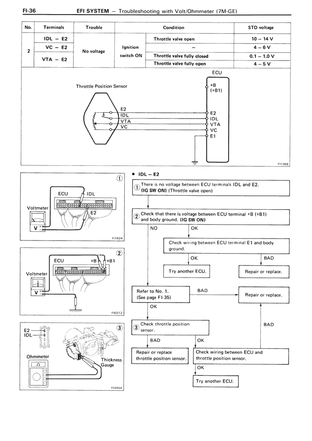
No. | Terminals | Trouble | Condition | STD voltage
1 | IDL — E2 | No voltage | Throttle valve open | 10 ~ 14 V
2 | VC — E2 | No voltage | Ignition switch ON | 4 ~ 6 V
  | VTA — E2 |          | Throttle valve fully closed | 0.1 ~ 1.0 V
  |          |          | Throttle valve fully open | 4 ~ 6 V

Throttle Position Sensor
[Diagram showing connections between Throttle Position Sensor and ECU with terminals E2, IDL, VTA, VC and ECU terminals +B (+B1), E2, IDL, VTA, VC, E1]

IDL — E2

1. There is no voltage between ECU terminals IDL and E2. (IG SW ON) (Throttle valve open)

2. Check that there is voltage between ECU terminal +B (+B1) and body ground. (IG SW ON)

NO | OK

Check wiring between ECU terminal E1 and body ground.

OK | BAD

Try another ECU. | Repair or replace.

BAD

Refer to No. 1. (See page FI-35) | Repair or replace.

OK

3. Check throttle position sensor.

BAD | OK

Repair or replace | Check wiring between ECU and throttle position sensor.

OK

Try another ECU.

[Diagram 1 (FI1624): Shows ECU with IDL and E2 connections to voltmeter]

[Diagram 2 (FI0512): Shows ECU with +B and +B1 connections to voltmeter]

[Diagram 3 (FI2434): Shows E2 and IDL connections to Ohmmeter with Thickness Gauge at throttle position sensor]