100%
EFI SYSTEM — Troubleshooting with Volt/Ohmmeter (7M-GTE) FI-59
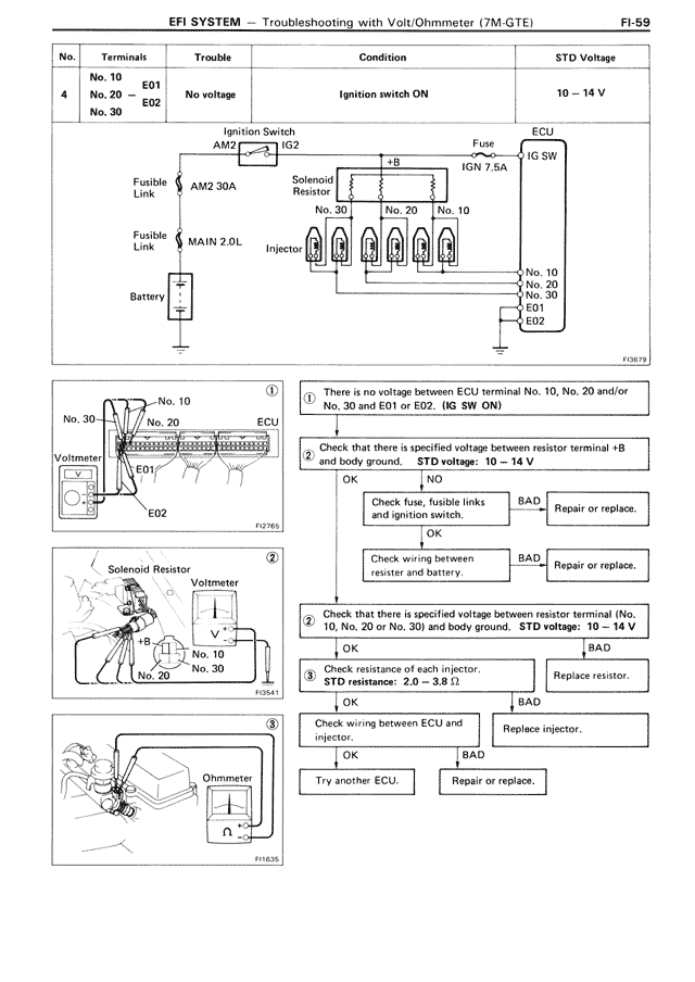
No. | Terminals | Trouble | Condition | STD Voltage
4 | No. 10
No. 20 ⟺ E01
No. 30 E02 | No voltage | Ignition switch ON | 10 – 14 V
[DIAGRAM showing circuit with Ignition Switch AM2, IG2, Fuse IGN 7.5A, ECU IG SW, Fusible Link AM2 30A, Solenoid Resistor, MAIN 2.0L, Injector, Battery, and connections to terminals No. 30, No. 20, No. 10, No. 10, No. 20, No. 30, E01, E02]
FD879
[DIAGRAM 1] No. 10, No. 30, ECU, E01, E02, Voltmeter showing connections
① There is no voltage between ECU terminal No. 10, No. 20 and/or No. 30 and E01 or E02. (IG SW ON)
② Check that there is specified voltage between resistor terminal +B and body ground. STD voltage: 10 – 14 V
OK | NO
Check fuse, fusible links and ignition switch. | BAD | Repair or replace.
OK
Check wiring between resistor and battery. | BAD | Repair or replace.
OK
[DIAGRAM 2] Solenoid Resistor with Voltmeter showing terminals +B, No. 10, No. 20, No. 30
FD541
② Check that there is specified voltage between resistor terminal (No. 10, No. 20 or No. 30) and body ground. STD voltage: 10 – 14 V
OK | BAD
③ Check resistance of each injector.
STD resistance: 2.0 – 3.8 Ω
OK | BAD
Replace resistor.
Check wiring between ECU and injector. | Replace injector.
OK | BAD
Try another ECU. | Repair or replace.
[DIAGRAM 3] Ohmmeter connection diagram
FI1635