100%
IGNITION SYSTEM — On-Vehicle Inspection (7M-GTE) IG-15
INSPECTION OF IGNITER
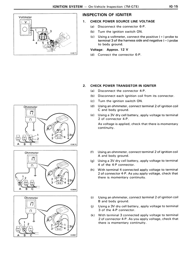
1. CHECK POWER SOURCE LINE VOLTAGE
(a) Disconnect the connector 6-P.
(b) Turn the ignition switch ON.
(c) Using a voltmeter, connect the positive (+) probe to terminal 3 of the harness side and negative (—) probe to body ground.
Voltage: Approx. 12 V
(d) Connect the connector 6-P.
2. CHECK POWER TRANSISTOR IN IGNITER
(a) Disconnect the connector 4-P.
(b) Disconnect each ignition coil from its connector.
(c) Turn the ignition switch ON.
(d) Using an ohmmeter, connect terminal 2 of ignition coil C and body ground.
(e) Using a 3V dry cell battery, apply voltage to terminal 2 of connector 4-P.
As voltage is applied, check that there is momentary continuity.
(f) Using an ohmmeter, connect terminal 2 of ignition coil A and body ground.
(g) Using a 3V dry cell battery, apply voltage to terminal 4 of the 4-P connector.
(h) With terminal 4 connected apply voltage to terminal 2 of connector 4-P. As you apply voltage, check that there is momentary continuity.
(i) Using an ohmmeter, connect terminal 2 of ignition coil B and body ground.
(j) Using a 3V dry cell battery, apply voltage to terminal 3 of the 4-P connector.
(k) With terminal 3 connected apply voltage to terminal 2 of connector 4-P. As you apply voltage, check that there is momentary continuity.