100%
Connector Joining Wire Harness and Wire Harness
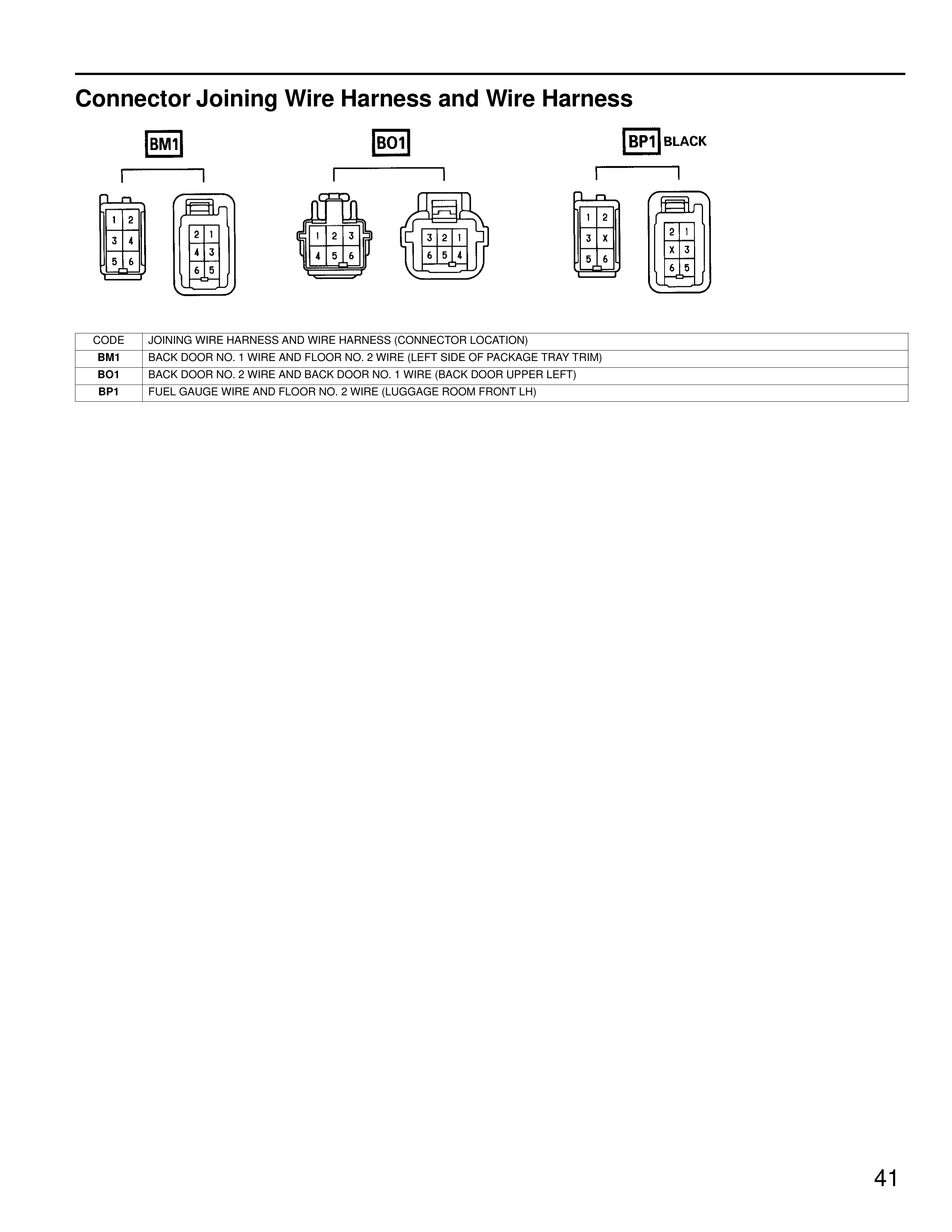
BM1
BO1
BP1 BLACK
[Connector BM1 - Left side shows 6-pin connector with pins numbered 1,2,3,4,5,6 and right side shows 6-pin connector with pins numbered 2,1,4,3,6,5]
[Connector BO1 - Left side shows 6-pin connector with pins numbered 1,2,3,4,5,6 and right side shows 6-pin connector with pins numbered 3,2,1,6,5,4]
[Connector BP1 - Left side shows 6-pin connector with pins numbered 1,2,3,X,5,6 and right side shows 6-pin connector with pins numbered 2,1,4,3,6,5]
CODE | JOINING WIRE HARNESS AND WIRE HARNESS (CONNECTOR LOCATION)
BM1 | BACK DOOR NO. 1 WIRE AND FLOOR NO. 2 WIRE (LEFT SIDE OF PACKAGE TRAY TRIM)
BO1 | BACK DOOR NO. 2 WIRE AND BACK DOOR NO. 1 WIRE (BACK DOOR UPPER LEFT)
BP1 | FUEL GAUGE WIRE AND FLOOR NO. 2 WIRE (LUGGAGE ROOM FRONT LH)
41