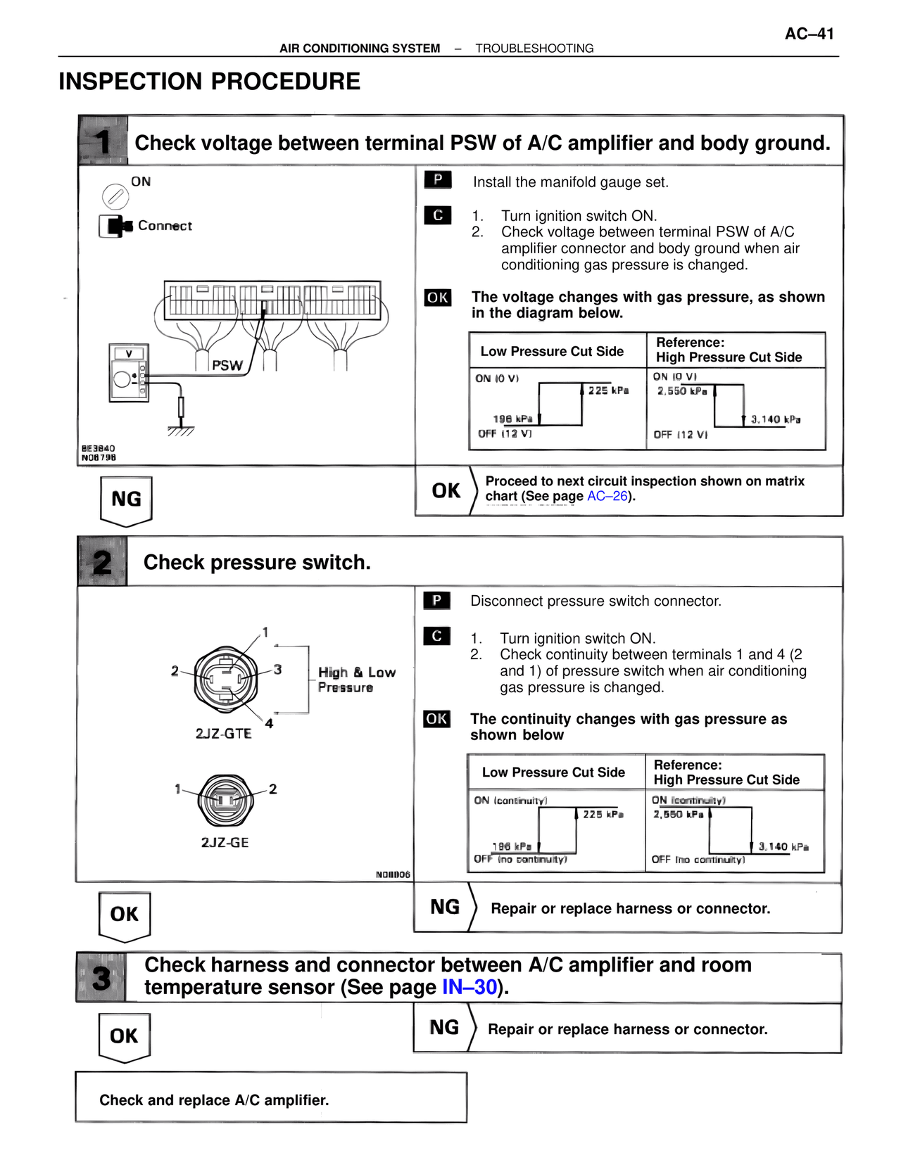
Page text (OCR transcript)
AC–41
AIR CONDITIONING SYSTEM – TROUBLESHOOTING

INSPECTION PROCEDURE

1 Check voltage between terminal PSW of A/C amplifier and body ground.

ON
Connect

PSW
8E3640
N08798

P Install the manifold gauge set.

C 1. Turn ignition switch ON.
2. Check voltage between terminal PSW of A/C amplifier connector and body ground when air conditioning gas pressure is changed.

OK The voltage changes with gas pressure, as shown in the diagram below.

Low Pressure Cut Side
ON (0 V)
225 kPa
196 kPa
OFF (12 V)

Reference:
High Pressure Cut Side
ON (0 V)
2,550 kPa
3,140 kPa
OFF (12 V)

NG

OK Proceed to next circuit inspection shown on matrix chart (See page AC–26).

2 Check pressure switch.

1
2 3 High & Low
Pressure
4
2JZ-GTE

1 2
2JZ-GE
N08806

P Disconnect pressure switch connector.

C 1. Turn ignition switch ON.
2. Check continuity between terminals 1 and 4 (2 and 1) of pressure switch when air conditioning gas pressure is changed.

OK The continuity changes with gas pressure as shown below

Low Pressure Cut Side
ON (continuity)
225 kPa
196 kPa
OFF (no continuity)

Reference:
High Pressure Cut Side
ON (continuity)
2,550 kPa
3,140 kPa
OFF (no continuity)

OK

NG Repair or replace harness or connector.

3 Check harness and connector between A/C amplifier and room temperature sensor (See page IN–30).

OK

NG Repair or replace harness or connector.

Check and replace A/C amplifier.