Page text (OCR transcript)
AC–53
AIR CONDITIONING SYSTEM – TROUBLESHOOTING

INSPECTION PROCEDURE

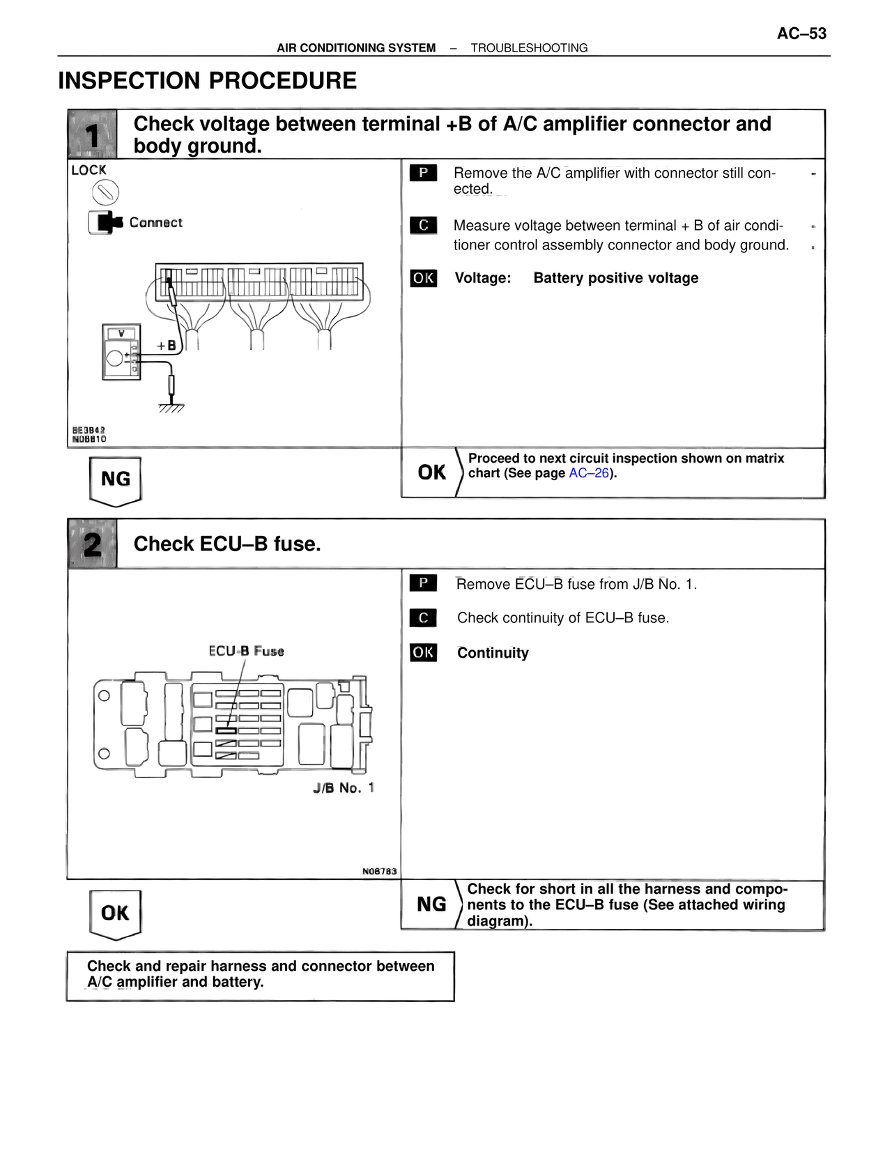
1  Check voltage between terminal +B of A/C amplifier connector and body ground.

LOCK
Connect

P  Remove the A/C amplifier with connector still connected.

C  Measure voltage between terminal + B of air conditioner control assembly connector and body ground.

OK  Voltage:  Battery positive voltage

+B

SE3842
N08810

NG                    OK  Proceed to next circuit inspection shown on matrix chart (See page AC–26).

2  Check ECU–B fuse.

ECU-B Fuse

P  Remove ECU–B fuse from J/B No. 1.

C  Check continuity of ECU–B fuse.

OK  Continuity

J/B No. 1

N08783

OK                    NG  Check for short in all the harness and components to the ECU–B fuse (See attached wiring diagram).

Check and repair harness and connector between A/C amplifier and battery.