Page text (OCR transcript)
AC–66
AIR CONDITIONING SYSTEM – TROUBLESHOOTING

A C Control Assembly Circuit

CIRCUIT DESCRIPTION

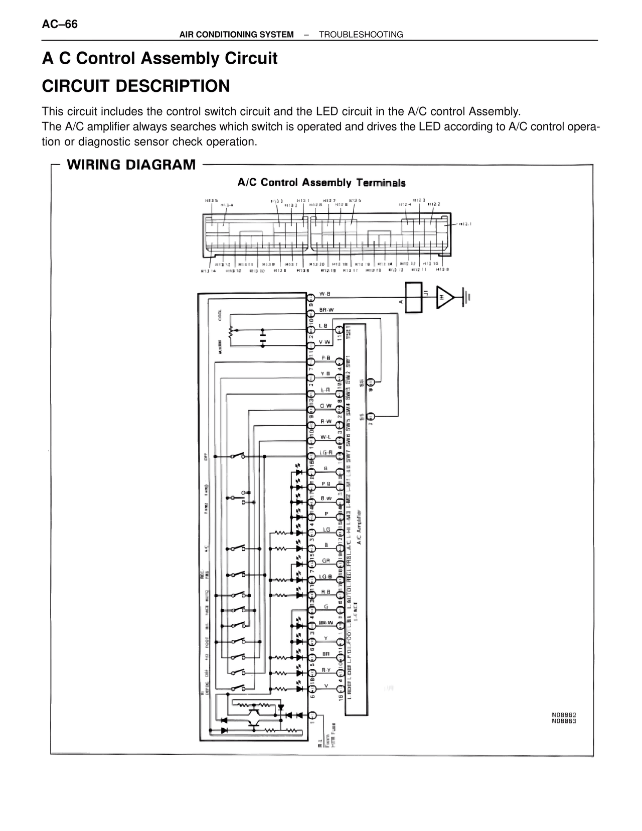
This circuit includes the control switch circuit and the LED circuit in the A/C control Assembly.
The A/C amplifier always searches which switch is operated and drives the LED according to A/C control operation or diagnostic sensor check operation.

— WIRING DIAGRAM —

A/C Control Assembly Terminals

H13.5
H13.4
H13.3  H13.2  H13.1  H12.7  H12.5        H12.3  H12.2
H12.8  H12.B                              H12.4
                                                    H12.1

H13.3  H13.11  H13.9  H13.7  H12.20  H12.18  H12.16  H12.14  H12.12  H12.10
H13.14  H13.12  H13.10  H13.8  H12.18  H12.11  H12.15  H12.13  H12.11  H12.9

W-B
BR-W
L.B
V-W
P-B
Y-B
LR
G-W
R-W
W-L
LG-R
R
P-R
B-W
P
LG
B
GR
LG-B
R-B
G
BR-W
Y
BR
B-Y
V

COOL
WARM
OFF
FAN1  FAN2
A/C
REC
FRE  AUTO
A/L  NOSE
DEF-OC  DEF  OAM

SW6  SW5  SW4  SW3  SW2  SW1
SW8
SW7

L-ACE
L-M1  LED  L-M2  L-M3
RECL  HEEL
A/C Amplifier

L-ROSE  L-DEF  L-OC  L-DE1  L-OD2

B-L
From
HTR Fuse

N08882
N08883