Page text (OCR transcript)
AC–70
AIR CONDITIONING SYSTEM – TROUBLESHOOTING

INSPECTION PROCEDURE

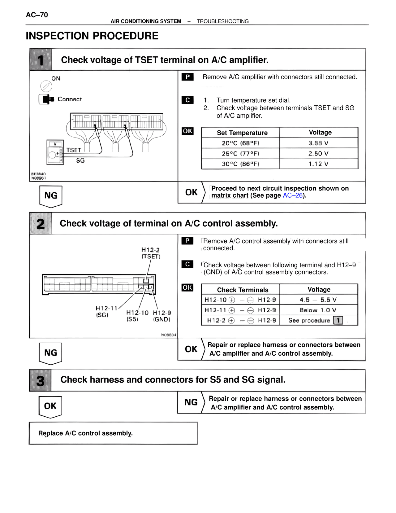
1 Check voltage of TSET terminal on A/C amplifier.

ON
Connect
TSET
SG
BE3840
N08961

P Remove A/C amplifier with connectors still connected.

C 1. Turn temperature set dial.
2. Check voltage between terminals TSET and SG of A/C amplifier.

OK
Set Temperature          Voltage
20°C (68°F)              3.88 V
25°C (77°F)              2.50 V
30°C (86°F)              1.12 V

NG

OK Proceed to next circuit inspection shown on matrix chart (See page AC–26).

2 Check voltage of terminal on A/C control assembly.

H12-2
(TSET)
H12-11    H12-10  H12-9
(SG)      (S5)    (GND)
N08834

P Remove A/C control assembly with connectors still connected.

C Check voltage between following terminal and H12–9 (GND) of A/C control assembly connectors.

OK
Check Terminals              Voltage
H12-10 ⊕ – ⊖ H12-9         4.5 – 5.5 V
H12-11 ⊕ – ⊖ H12-9         Below 1.0 V
H12-2 ⊕ – ⊖ H12-9          See procedure 1.

NG

OK Repair or replace harness or connectors between A/C amplifier and A/C control assembly.

3 Check harness and connectors for S5 and SG signal.

OK

NG Repair or replace harness or connectors between A/C amplifier and A/C control assembly.

Replace A/C control assembly.