100%
AT1–36
AT340E (2JZ–GE) AUTOMATIC TRANSMISSION – TROUBLESHOOTING
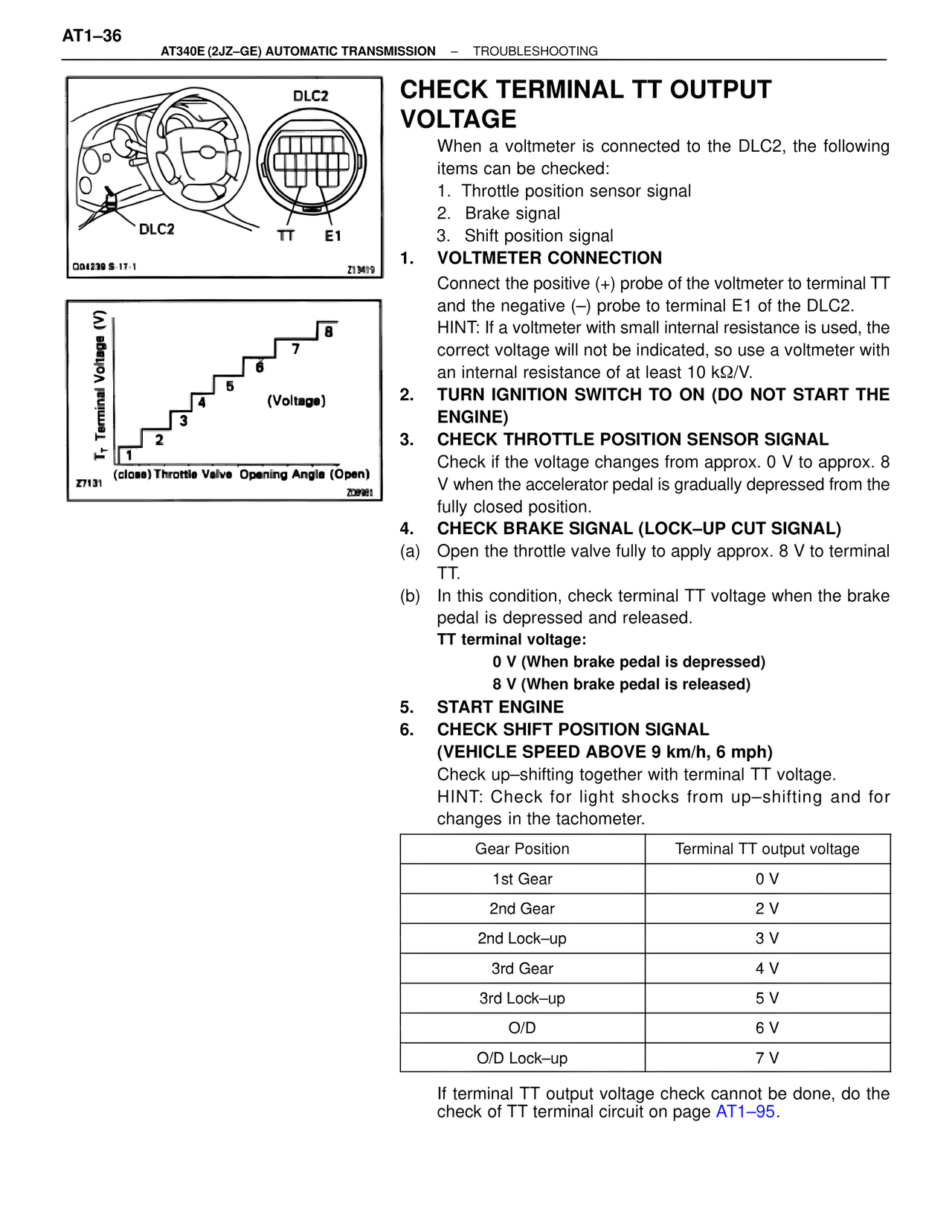
DLC2
DLC2 TT E1
O04239 S-17-1 Z13409
T_T Terminal Voltage (V)
8
7
6
5
4
3
2
1
(Voltage)
(close) Throttle Valve Opening Angle (Open)
Z7131 Z09981
CHECK TERMINAL TT OUTPUT VOLTAGE
When a voltmeter is connected to the DLC2, the following items can be checked:
1. Throttle position sensor signal
2. Brake signal
3. Shift position signal
1. VOLTMETER CONNECTION
Connect the positive (+) probe of the voltmeter to terminal TT and the negative (–) probe to terminal E1 of the DLC2.
HINT: If a voltmeter with small internal resistance is used, the correct voltage will not be indicated, so use a voltmeter with an internal resistance of at least 10 kΩ/V.
2. TURN IGNITION SWITCH TO ON (DO NOT START THE ENGINE)
3. CHECK THROTTLE POSITION SENSOR SIGNAL
Check if the voltage changes from approx. 0 V to approx. 8 V when the accelerator pedal is gradually depressed from the fully closed position.
4. CHECK BRAKE SIGNAL (LOCK–UP CUT SIGNAL)
(a) Open the throttle valve fully to apply approx. 8 V to terminal TT.
(b) In this condition, check terminal TT voltage when the brake pedal is depressed and released.
TT terminal voltage:
0 V (When brake pedal is depressed)
8 V (When brake pedal is released)
5. START ENGINE
6. CHECK SHIFT POSITION SIGNAL
(VEHICLE SPEED ABOVE 9 km/h, 6 mph)
Check up–shifting together with terminal TT voltage.
HINT: Check for light shocks from up–shifting and for changes in the tachometer.
Gear Position Terminal TT output voltage
1st Gear 0 V
2nd Gear 2 V
2nd Lock–up 3 V
3rd Gear 4 V
3rd Lock–up 5 V
O/D 6 V
O/D Lock–up 7 V
If terminal TT output voltage check cannot be done, do the check of TT terminal circuit on page AT1–95.