100%
AT1–67
AT340E (2JZ–GE) AUTOMATIC TRANSMISSION – TROUBLESHOOTING
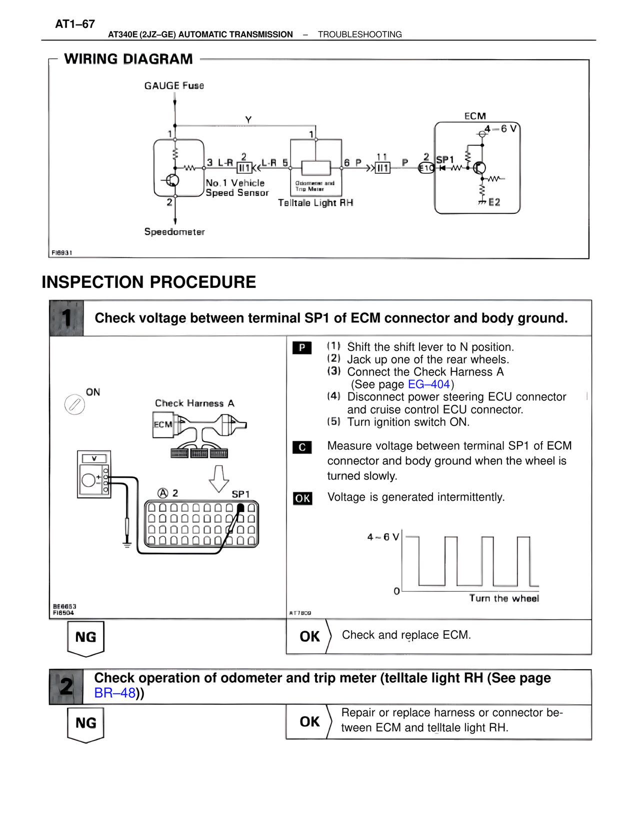
WIRING DIAGRAM
GAUGE Fuse
Y
1 1 ECM
4~6 V
3 L-R 2 L-R 5 6 P 11 P 2 SP1
II1 II1 E10
No.1 Vehicle
Speed Sensor Odometer and
Trip Meter
2 Telltale Light RH
E2
Speedometer
FI6931
INSPECTION PROCEDURE
1 Check voltage between terminal SP1 of ECM connector and body ground.
ON
Check Harness A
ECM
P (1) Shift the shift lever to N position.
(2) Jack up one of the rear wheels.
(3) Connect the Check Harness A
(See page EG–404)
(4) Disconnect power steering ECU connector
and cruise control ECU connector.
(5) Turn ignition switch ON.
A 2 SP1
C Measure voltage between terminal SP1 of ECM
connector and body ground when the wheel is
turned slowly.
OK Voltage is generated intermittently.
4~6 V
0
Turn the wheel
BE6653
FI6504 AT7809
NG OK Check and replace ECM.
2 Check operation of odometer and trip meter (telltale light RH (See page
BR–48))
NG OK Repair or replace harness or connector be-
tween ECM and telltale light RH.