100%
Page text (OCR transcript)
AT1–81

AT340E (2JZ–GE) AUTOMATIC TRANSMISSION – TROUBLESHOOTING

Park Neutral Position Switch Circuit

CIRCUIT DESCRIPTION

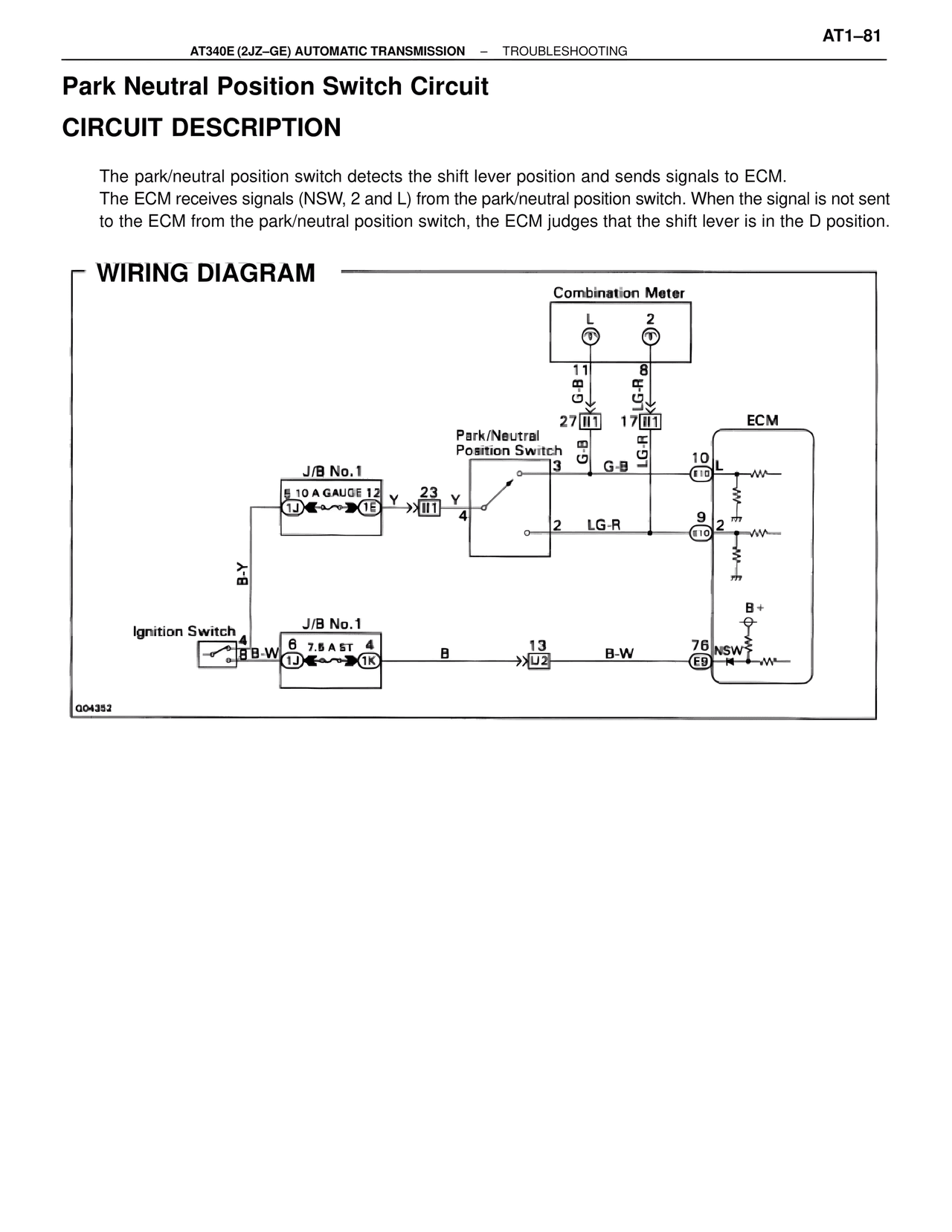
The park/neutral position switch detects the shift lever position and sends signals to ECM.
The ECM receives signals (NSW, 2 and L) from the park/neutral position switch. When the signal is not sent
to the ECM from the park/neutral position switch, the ECM judges that the shift lever is in the D position.

WIRING DIAGRAM

Combination Meter
L
2

11
G-B
8
LG-R
27 II1
17 II1

Park/Neutral
Position Switch
3
G-B
G-B
LG-R

ECM
10 L
E10

J/B No.1
5 10 A GAUGE 12
1J
1E
Y
23
Y
>>II1
4

9
2
E10

2
LG-R

B-Y

B+

Ignition Switch
4
B B-W

J/B No.1
6 7.5 A ST
4
1J
1K
B
13
>>U2
B-W
76 NSW
E9

G04352