100%
AT-7
A340E (2JZ-GTE) AUTOMATIC TRANSMISSION - OPERATION
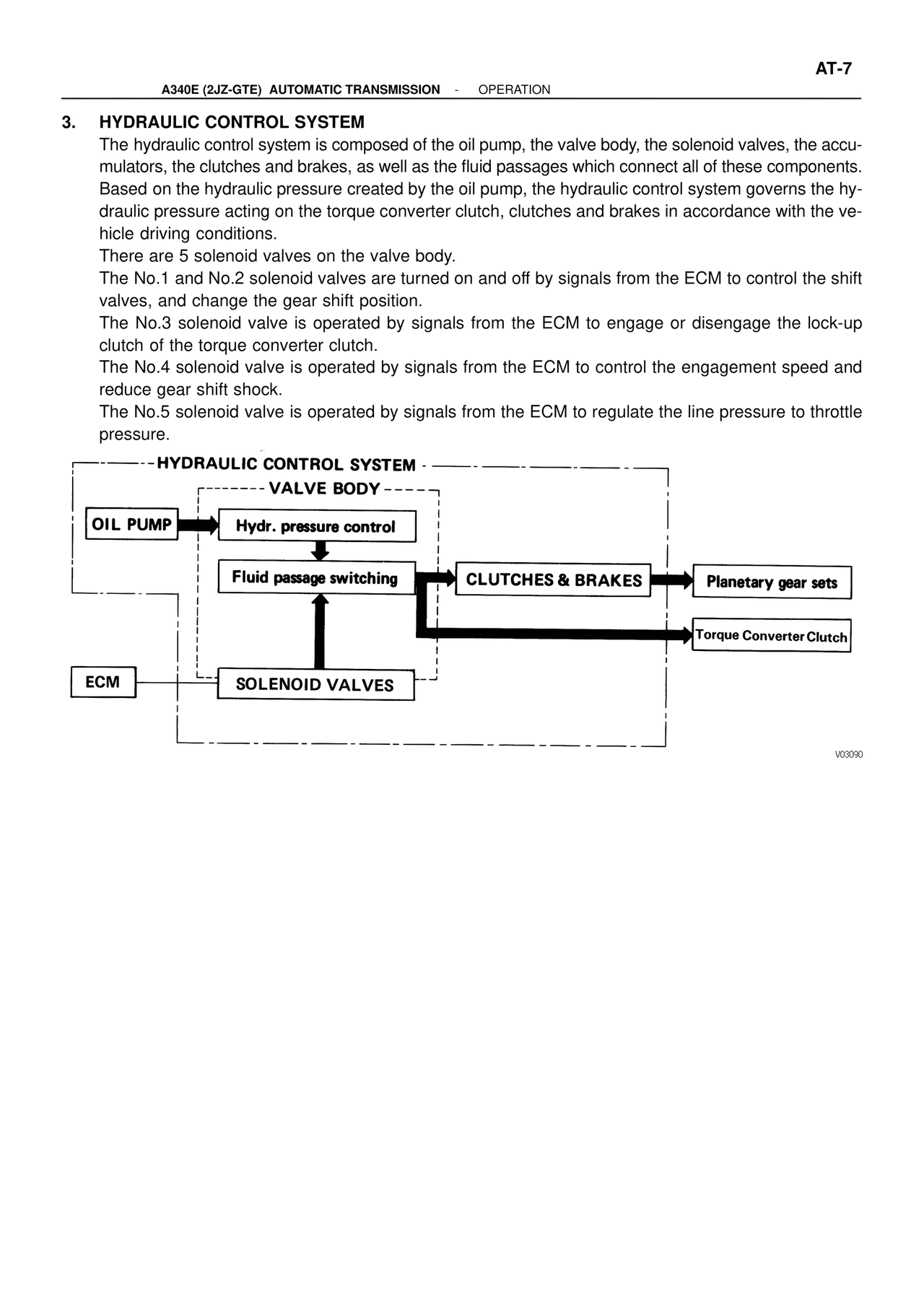
3. HYDRAULIC CONTROL SYSTEM
The hydraulic control system is composed of the oil pump, the valve body, the solenoid valves, the accu-
mulators, the clutches and brakes, as well as the fluid passages which connect all of these components.
Based on the hydraulic pressure created by the oil pump, the hydraulic control system governs the hy-
draulic pressure acting on the torque converter clutch, clutches and brakes in accordance with the ve-
hicle driving conditions.
There are 5 solenoid valves on the valve body.
The No.1 and No.2 solenoid valves are turned on and off by signals from the ECM to control the shift
valves, and change the gear shift position.
The No.3 solenoid valve is operated by signals from the ECM to engage or disengage the lock-up
clutch of the torque converter clutch.
The No.4 solenoid valve is operated by signals from the ECM to control the engagement speed and
reduce gear shift shock.
The No.5 solenoid valve is operated by signals from the ECM to regulate the line pressure to throttle
pressure.
- - - - - - HYDRAULIC CONTROL SYSTEM - - - - - - - - - - - - - - -
- - - - - - - - VALVE BODY - - - - - -
OIL PUMP → Hydr. pressure control
↓
Fluid passage switching → CLUTCHES & BRAKES → Planetary gear sets
↑ ↘ Torque Converter Clutch
ECM → SOLENOID VALVES
V03090