100%
AT2–10
A340E (2JZ—GTE) AUTOMATIC TRANSMISSION – OPERATION
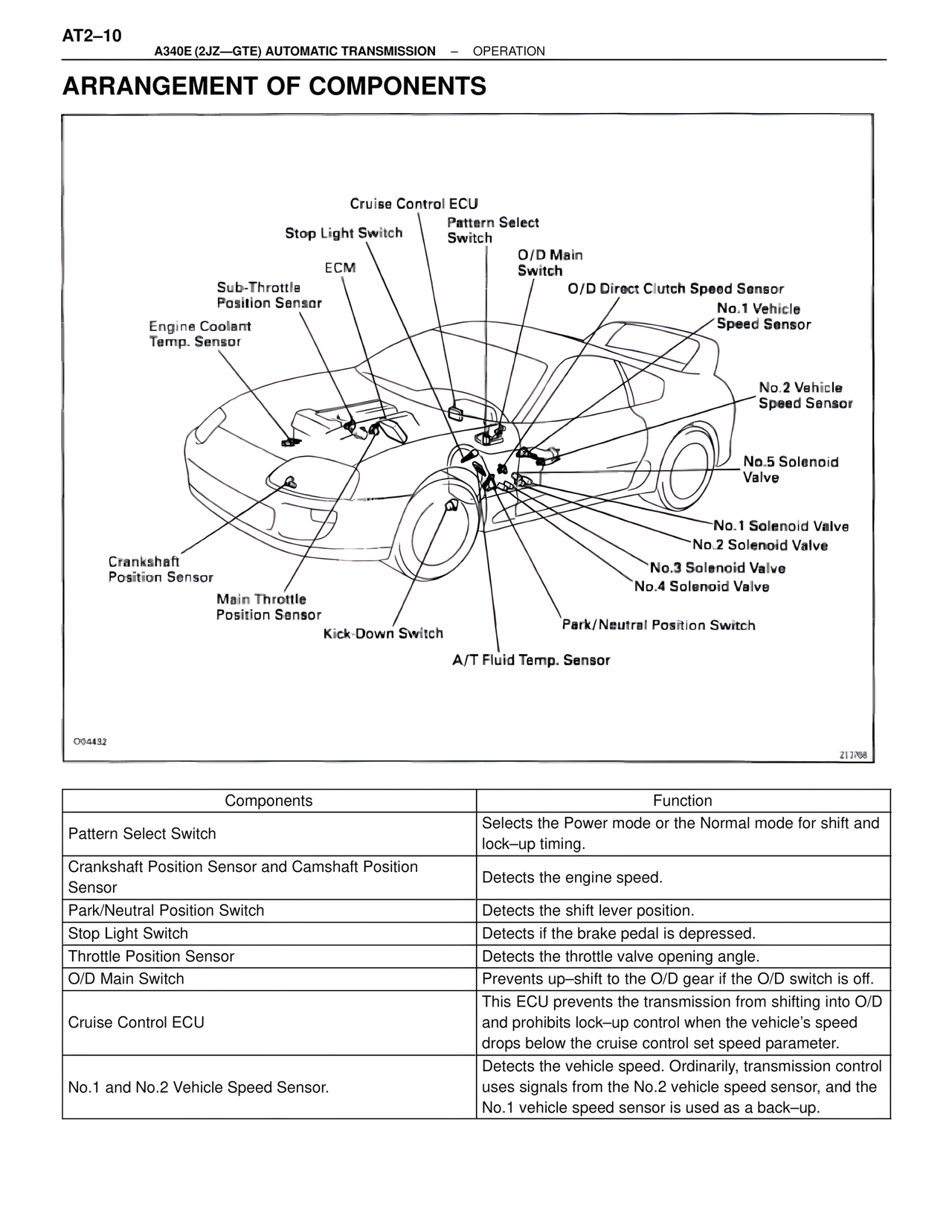
ARRANGEMENT OF COMPONENTS
Cruise Control ECU
Stop Light Switch
Pattern Select Switch
O/D Main Switch
ECM
O/D Direct Clutch Speed Sensor
Sub-Throttle Position Sensor
No.1 Vehicle Speed Sensor
Engine Coolant Temp. Sensor
No.2 Vehicle Speed Sensor
No.5 Solenoid Valve
No.1 Solenoid Valve
No.2 Solenoid Valve
No.3 Solenoid Valve
No.4 Solenoid Valve
Crankshaft Position Sensor
Park/Neutral Position Switch
Main Throttle Position Sensor
Kick-Down Switch
A/T Fluid Temp. Sensor
O04432
213768
Components | Function
Pattern Select Switch | Selects the Power mode or the Normal mode for shift and lock–up timing.
Crankshaft Position Sensor and Camshaft Position Sensor | Detects the engine speed.
Park/Neutral Position Switch | Detects the shift lever position.
Stop Light Switch | Detects if the brake pedal is depressed.
Throttle Position Sensor | Detects the throttle valve opening angle.
O/D Main Switch | Prevents up–shift to the O/D gear if the O/D switch is off.
Cruise Control ECU | This ECU prevents the transmission from shifting into O/D and prohibits lock–up control when the vehicle's speed drops below the cruise control set speed parameter.
No.1 and No.2 Vehicle Speed Sensor. | Detects the vehicle speed. Ordinarily, transmission control uses signals from the No.2 vehicle speed sensor, and the No.1 vehicle speed sensor is used as a back–up.