100%
AT2–103
A340E (2JZ—GTE) AUTOMATIC TRANSMISSION – TROUBLESHOOTING
Stop Light Switch Circuit
— CIRCUIT DESCRIPTION —
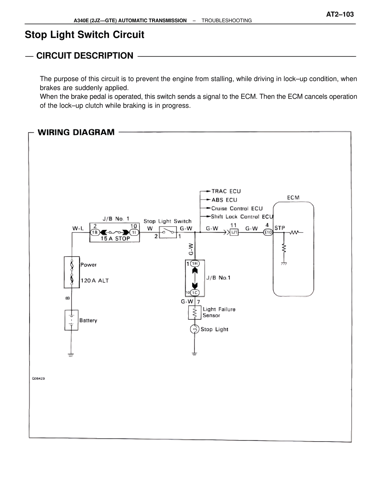
The purpose of this circuit is to prevent the engine from stalling, while driving in lock–up condition, when brakes are suddenly applied.
When the brake pedal is operated, this switch sends a signal to the ECM. Then the ECM cancels operation of the lock–up clutch while braking is in progress.
— WIRING DIAGRAM —
J/B No. 1
W-L 2 10
1B 11
15 A STOP
Stop Light Switch
W G-W
2 1
G-W
1 (1H)
10 (1C)
J/B No.1
G-W 7
Light Failure Sensor
Stop Light
Power
120 A ALT
Battery
TRAC ECU
ABS ECU
Cruise Control ECU
Shift Lock Control ECU
G-W 11 G-W 4 STP
J1 E10
ECM
C05429