Page text (OCR transcript)
AT2–80
A340E (2JZ—GTE) AUTOMATIC TRANSMISSION – TROUBLESHOOTING

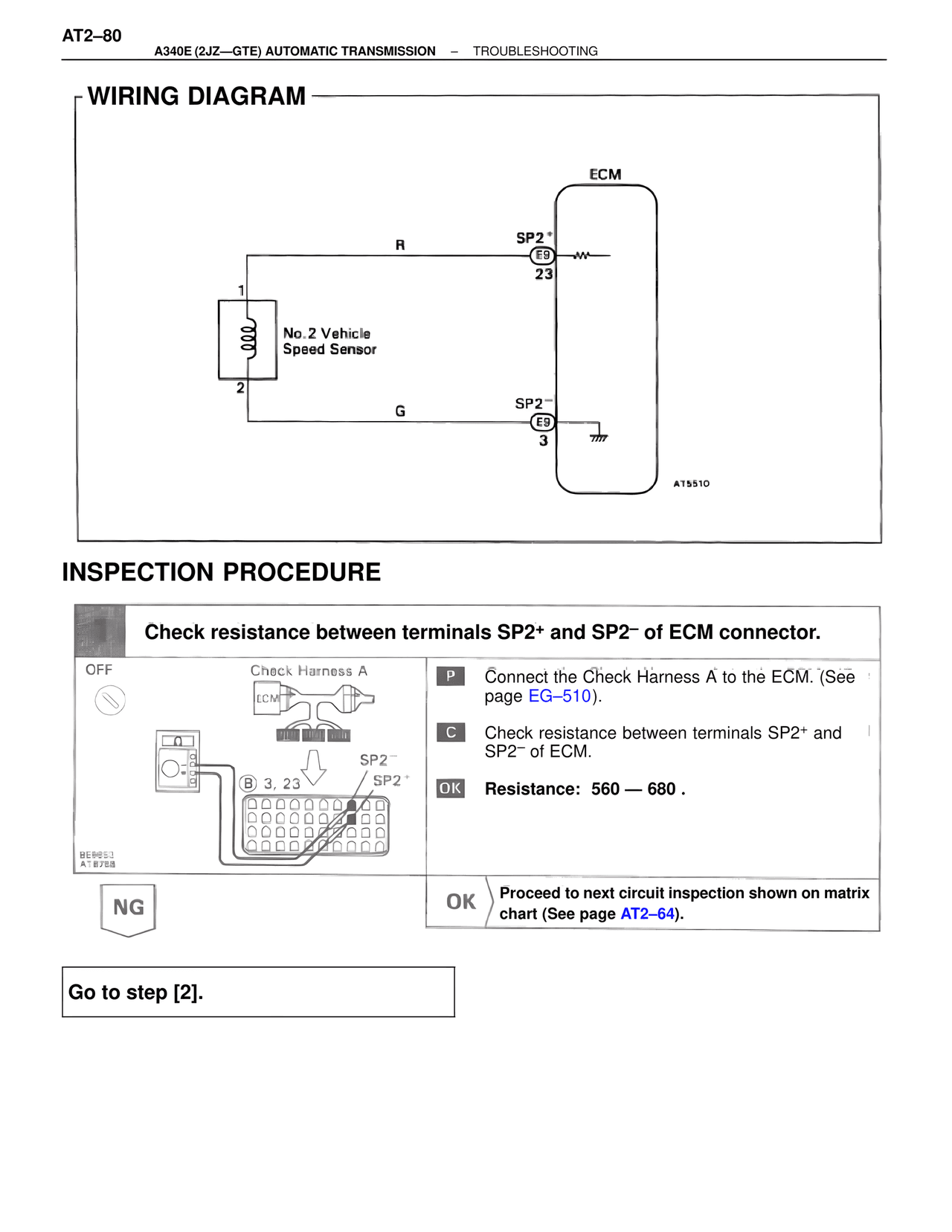
WIRING DIAGRAM

ECM

R                    SP2+
                     E9
                     23
1
No. 2 Vehicle
Speed Sensor
2

G                    SP2–
                     E9
                     3

AT5510

INSPECTION PROCEDURE

Check resistance between terminals SP2+ and SP2– of ECM connector.

OFF
Check Harness A
ECM

SP2–
B 3, 23        SP2+

BE6653
AT8758

P    Connect the Check Harness A to the ECM. (See page EG–510).

C    Check resistance between terminals SP2+ and SP2– of ECM.

OK   Resistance: 560 — 680 .

NG

OK   Proceed to next circuit inspection shown on matrix chart (See page AT2–64).

Go to step [2].