← p.084p.086 →
ATTE/A340 Automatic Trans (GTE) — Dtc 64 No. 3 Solenoid Valve Circuit (For Lock–up Control Pressure Modulation), page 85
85 / 118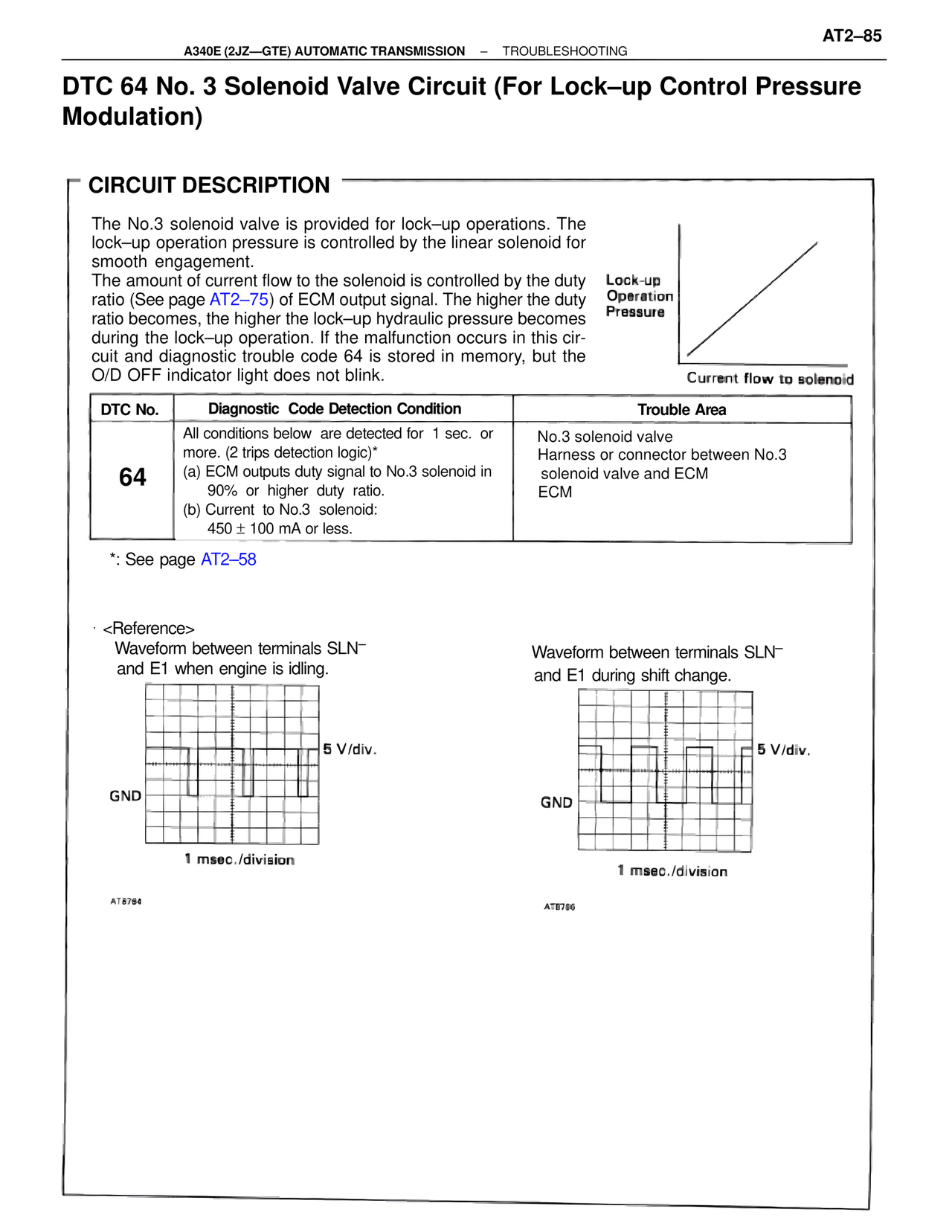
100%
Page text (OCR transcript)
AT2–85

A340E (2JZ—GTE) AUTOMATIC TRANSMISSION  –  TROUBLESHOOTING

DTC 64 No. 3 Solenoid Valve Circuit (For Lock–up Control Pressure Modulation)

CIRCUIT DESCRIPTION

The No.3 solenoid valve is provided for lock–up operations. The lock–up operation pressure is controlled by the linear solenoid for smooth engagement.
The amount of current flow to the solenoid is controlled by the duty ratio (See page AT2–75) of ECM output signal. The higher the duty ratio becomes, the higher the lock–up hydraulic pressure becomes during the lock–up operation. If the malfunction occurs in this circuit and diagnostic trouble code 64 is stored in memory, but the O/D OFF indicator light does not blink.

Lock-up
Operation
Pressure

Current flow to solenoid

DTC No.    Diagnostic  Code Detection Condition    Trouble Area

64
All conditions below  are detected for  1 sec.  or more. (2 trips detection logic)*
(a) ECM outputs duty signal to No.3 solenoid in 90%  or  higher  duty  ratio.
(b) Current  to No.3  solenoid:
450 ± 100 mA or less.

No.3 solenoid valve
Harness or connector between No.3 solenoid valve and ECM
ECM

*: See page AT2–58

<Reference>
Waveform between terminals SLN–
and E1 when engine is idling.

5 V/div.
GND
1 msec./division
AT8784

Waveform between terminals SLN–
and E1 during shift change.

5 V/div.
GND
1 msec./division
AT8786