Page text (OCR transcript)
INSPECTION PROCEDURE

1  Check No.3 solenoid valve.

Check solenoid resistance

P  1. Jack up the vehicle.
   2. Remove the oil pan.
   3. Disconnect the solenoid connector

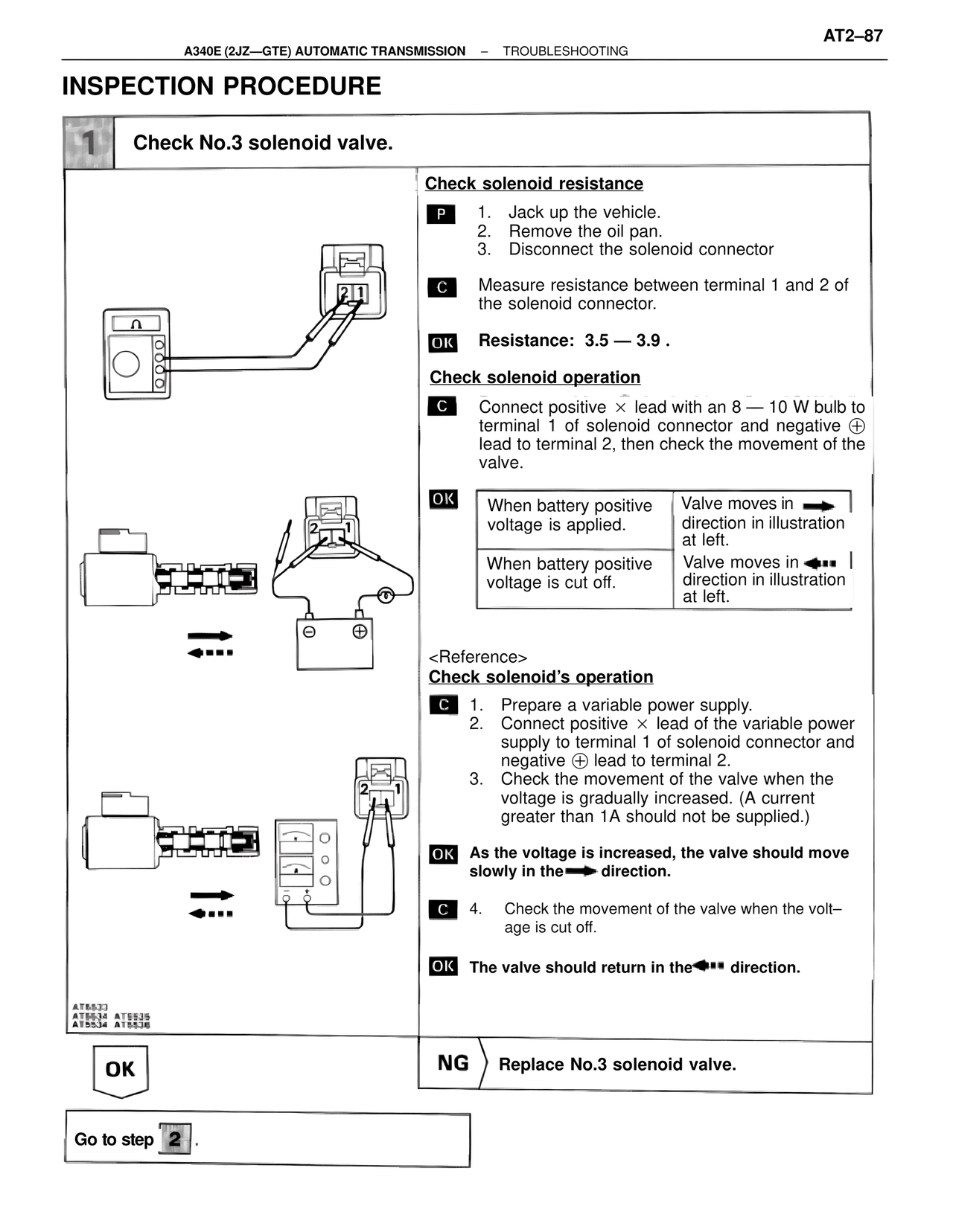
C  Measure resistance between terminal 1 and 2 of the solenoid connector.

OK  Resistance: 3.5 — 3.9 .

Check solenoid operation

C  Connect positive × lead with an 8 — 10 W bulb to terminal 1 of solenoid connector and negative ⊕ lead to terminal 2, then check the movement of the valve.

OK
When battery positive voltage is applied. | Valve moves in ➡ direction in illustration at left.
When battery positive voltage is cut off. | Valve moves in ⬅••• direction in illustration at left.

<Reference>
Check solenoid's operation

C  1. Prepare a variable power supply.
   2. Connect positive × lead of the variable power supply to terminal 1 of solenoid connector and negative ⊕ lead to terminal 2.
   3. Check the movement of the valve when the voltage is gradually increased. (A current greater than 1A should not be supplied.)

OK  As the voltage is increased, the valve should move slowly in the ➡ direction.

C  4. Check the movement of the valve when the voltage is cut off.

OK  The valve should return in the ⬅••• direction.

AT5533
AT5534 AT5535
AT5534 AT5536

OK                    NG  Replace No.3 solenoid valve.

Go to step 2 .