100%
AT2–90
A340E (2JZ—GTE) AUTOMATIC TRANSMISSION – TROUBLESHOOTING
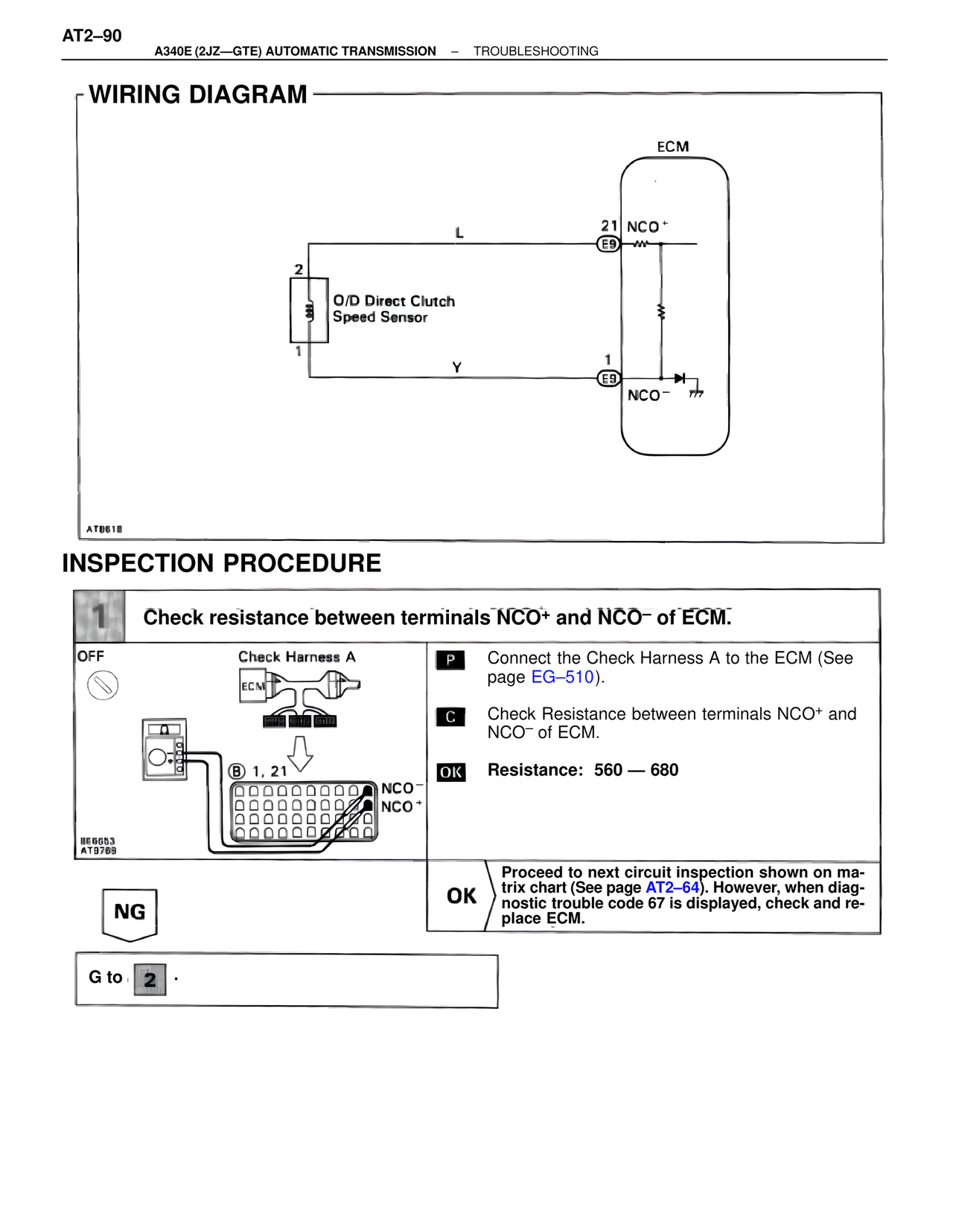
WIRING DIAGRAM
ECM
L
21 NCO+
E9
2
O/D Direct Clutch
Speed Sensor
1
Y
1
E9
NCO-
ATB618
INSPECTION PROCEDURE
1 Check resistance between terminals NCO+ and NCO- of ECM.
OFF Check Harness A
ECM
B 1, 21
NCO-
NCO+
BE6653
AT9769
P Connect the Check Harness A to the ECM (See page EG–510).
C Check Resistance between terminals NCO+ and NCO- of ECM.
OK Resistance: 560 — 680
NG
OK Proceed to next circuit inspection shown on matrix chart (See page AT2–64). However, when diagnostic trouble code 67 is displayed, check and replace ECM.
G to 2 .