100%
AT2–92
A340E (2JZ—GTE) AUTOMATIC TRANSMISSION – TROUBLESHOOTING
DTC 77 No.5 Solenoid Valve Circuit (For Line Pressure Modulation)
CIRCUIT DESCRIPTION
The throttle pressure that is applied to the primary regulator valve (which modulates line pressure) causes the
No.5 solenoid valve, under electronic control, to precisely and minutely modulate and generate line pressure
according to the accelerator pedal effort, or engine power output detected. This reduces the fluctuation of line
pressure and provides smooth shifting characteristics.
Upon receiving the throttle valve opening angle signal, ECM controls the line pressure by sending a predeter-
mined duty ratio to the No.5 solenoid valve located in the valve body, activating the solenoid valve, modulating
the line pressure, generating throttle pressure.
DTC No. | Diagnostic Trouble Code Detection Condition | Trouble Area
77 | Any of condition below are detected. (2 trip detection logic)
SLT⁻ terminal: 0 V or 5 V for 1 sec. or more. | No.5 solenoid valve
Harness or connector between No.5 solenoid valve and ECM
ECM
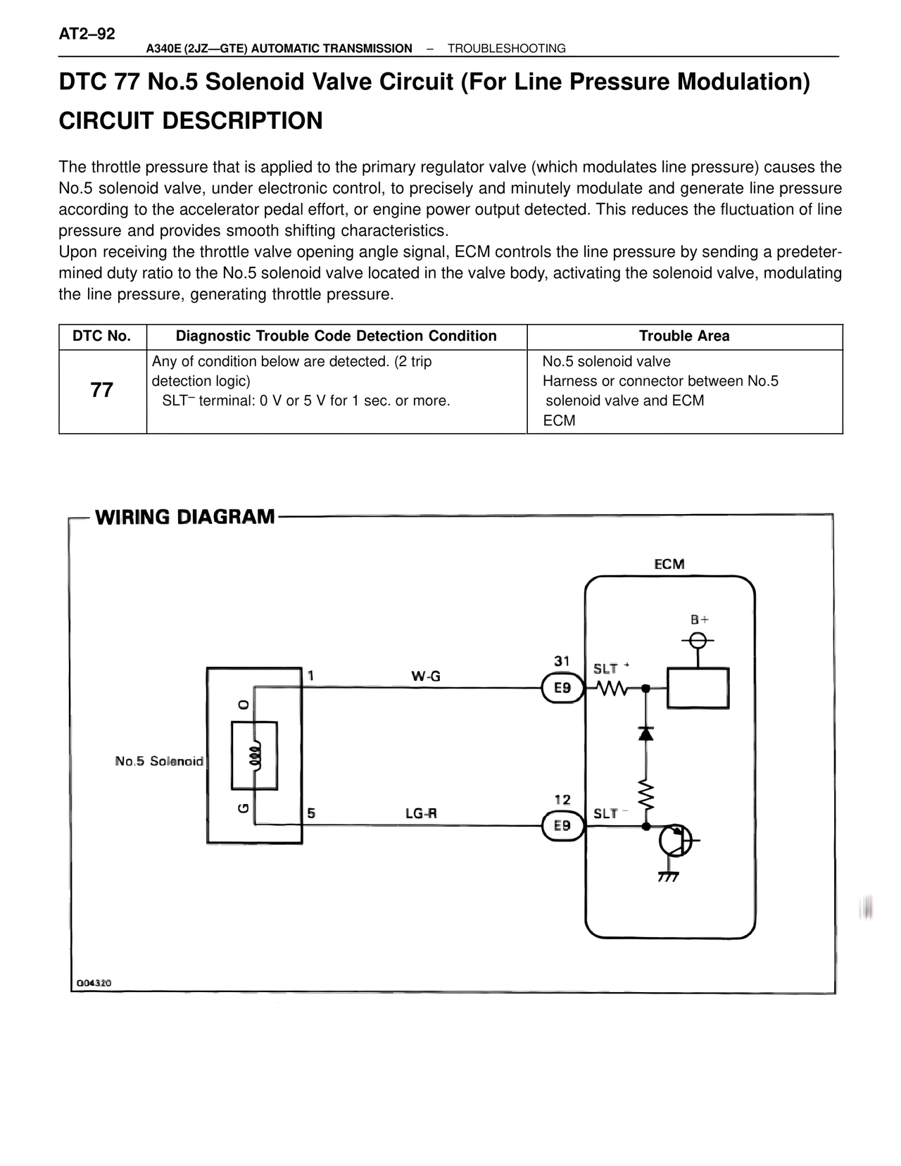
WIRING DIAGRAM
ECM
B+
31
W-G
1
E9 SLT +
No.5 Solenoid
12
5 LG-R
E9 SLT⁻
G04320