100%
BR–103
BRAKE SYSTEM – ANTI–LOCK BRAKE SYSTEM (ABS)
INSPECTION PROCEDURE.
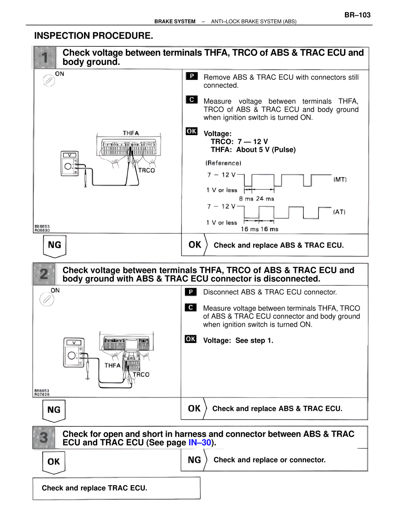
1 Check voltage between terminals THFA, TRCO of ABS & TRAC ECU and body ground.
ON
THFA
TRCO
BE6653
R05930
P Remove ABS & TRAC ECU with connectors still connected.
C Measure voltage between terminals THFA, TRCO of ABS & TRAC ECU and body ground when ignition switch is turned ON.
OK Voltage:
TRCO: 7 — 12 V
THFA: About 5 V (Pulse)
(Reference)
7 – 12 V (MT)
1 V or less
8 ms 24 ms
7 – 12 V (AT)
1 V or less
16 ms 16 ms
NG OK ) Check and replace ABS & TRAC ECU.
2 Check voltage between terminals THFA, TRCO of ABS & TRAC ECU and body ground with ABS & TRAC ECU connector is disconnected.
ON
THFA TRCO
BE6653
R07826
P Disconnect ABS & TRAC ECU connector.
C Measure voltage between terminals THFA, TRCO of ABS & TRAC ECU connector and body ground when ignition switch is turned ON.
OK Voltage: See step 1.
NG OK ) Check and replace ABS & TRAC ECU.
3 Check for open and short in harness and connector between ABS & TRAC ECU and TRAC ECU (See page IN–30).
OK NG ) Check and replace or connector.
Check and replace TRAC ECU.