Page text (OCR transcript)
BR–105

BRAKE SYSTEM – ANTI–LOCK BRAKE SYSTEM (ABS)

Stop Light Switch Circuit

CIRCUIT DESCRIPTION
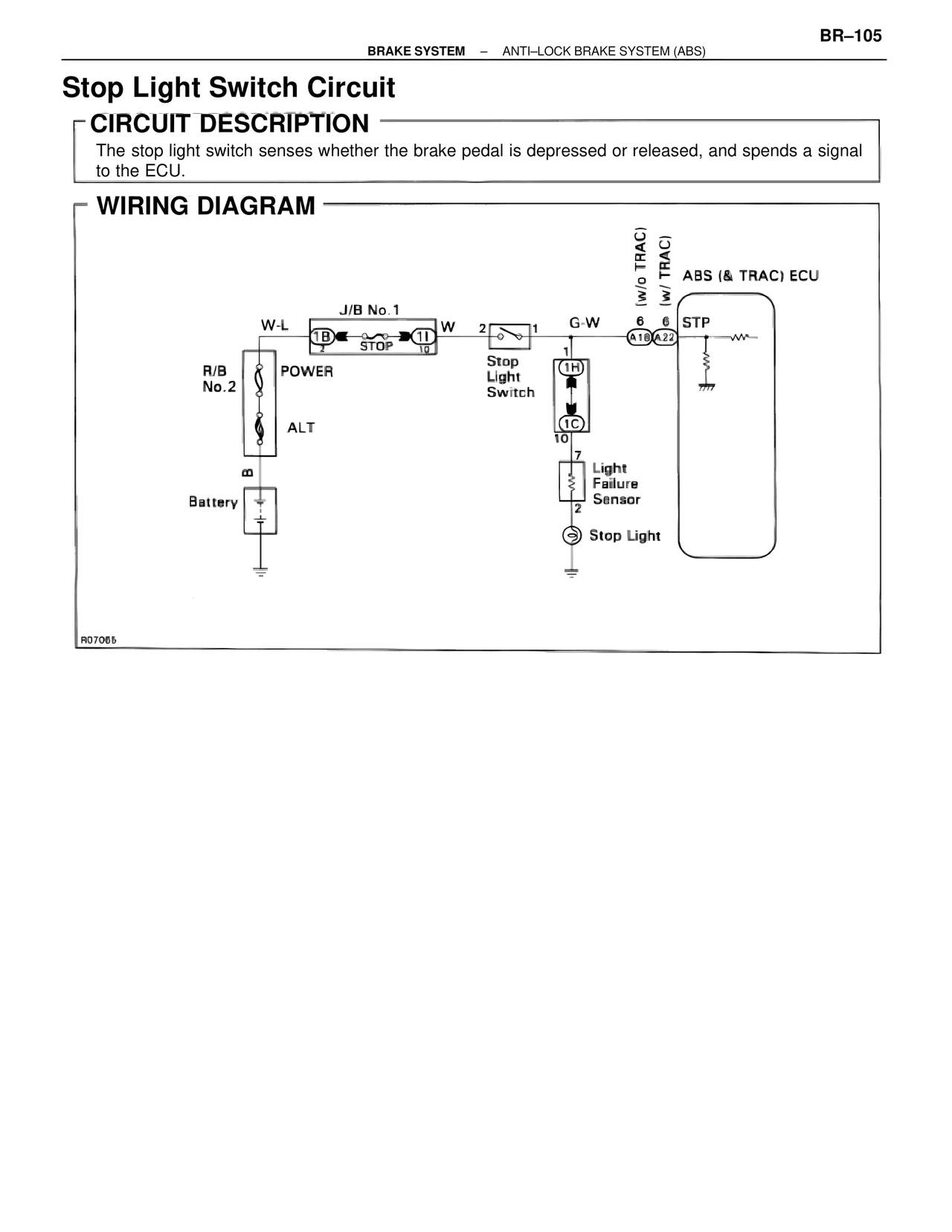
The stop light switch senses whether the brake pedal is depressed or released, and spends a signal
to the ECU.

WIRING DIAGRAM

W-L
J/B No.1
1B STOP 1I W 2 1 G-W 6 6 STP ABS (& TRAC) ECU
(w/o TRAC)
(w/ TRAC)
A18 A22

R/B
No.2
POWER

Stop
Light
Switch
1H

ALT
1C
10
7
Light
Failure
Sensor
B
2
Battery
Stop Light

R07065