100%
BR–107
BRAKE SYSTEM – ANTI–LOCK BRAKE SYSTEM (ABS)
ABS Warning Light Circuit
CIRCUIT DESCRIPTION
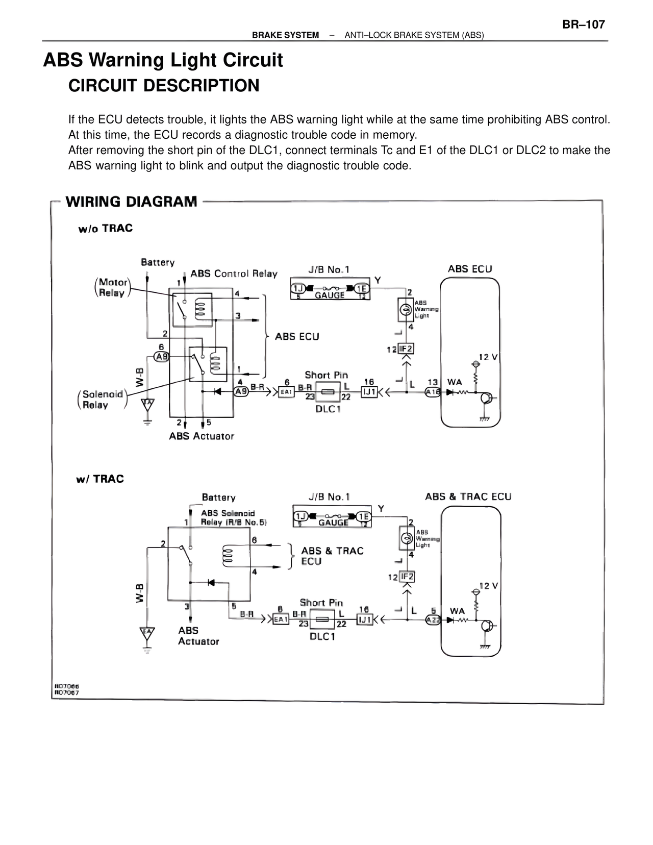
If the ECU detects trouble, it lights the ABS warning light while at the same time prohibiting ABS control.
At this time, the ECU records a diagnostic trouble code in memory.
After removing the short pin of the DLC1, connect terminals Tc and E1 of the DLC1 or DLC2 to make the
ABS warning light to blink and output the diagnostic trouble code.
WIRING DIAGRAM
w/o TRAC
Battery
ABS Control Relay
J/B No.1
ABS ECU
(Motor
Relay)
1
4
1J
1E
GAUGE
2
ABS
Warning
Light
3
2
4
L
A9
W-B
12
IF2
1
4
Short Pin
12 V
(Solenoid
Relay)
A9
B-R
EA1
B-R
L
16
L
13
WA
23
22
IJ1
A18
DLC1
2
5
ABS Actuator
w/ TRAC
Battery
J/B No.1
ABS & TRAC ECU
ABS Solenoid
Relay (R/B No.5)
1J
1E
1
GAUGE
2
ABS
Warning
Light
2
6
ABS & TRAC
4
ECU
4
W-B
L
12
IF2
3
Short Pin
12 V
5
B-R
6
B-R
L
16
L
5
WA
EA1
23
22
IJ1
A22
DLC1
ABS
Actuator
R07066
R07067