100%
BR–110
BRAKE SYSTEM – ANTI–LOCK BRAKE SYSTEM (ABS)
INSPECTION PROCEDURE (w/ TRAC)
Troubleshoot in accordance with the chart below for each trouble symptom.
ABS warning light does not light up | Go to step [1]
ABS warning light remains on | Go to step [3]
1 Check ABS warning light.
See Combination Meter Troubleshooting on page BE–43.
OK
NG Replace bulb or combination meter assembly.
2 Check ABS solenoid relay.
Open
3 2 1
Continuity
Continuity
6 5 4
Continuity
3 2 1
Open
6 5 4
3 2 1
6 5 4
BR5404
BR5406
RO7081
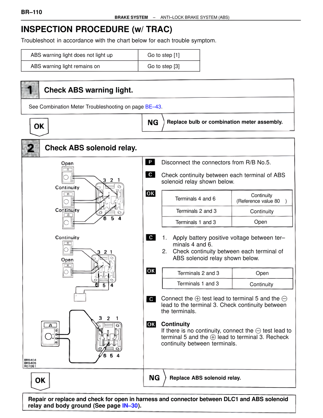
P Disconnect the connectors from R/B No.5.
C Check continuity between each terminal of ABS solenoid relay shown below.
OK
Terminals 4 and 6 | Continuity (Reference value 80 )
Terminals 2 and 3 | Continuity
Terminals 1 and 3 | Open
C 1. Apply battery positive voltage between ter–minals 4 and 6.
2. Check continuity between each terminal of ABS solenoid relay shown below.
OK
Terminals 2 and 3 | Open
Terminals 1 and 3 | Continuity
C Connect the ⊕ test lead to terminal 5 and the ⊖ lead to the terminal 3. Check continuity between the terminals.
OK Continuity
If there is no continuity, connect the ⊖ test lead to terminal 5 and the ⊕ lead to terminal 3. Recheck continuity between terminals.
OK
NG Replace ABS solenoid relay.
Repair or replace and check for open in harness and connector between DLC1 and ABS solenoid relay and body ground (See page IN–30).