100%
BR–112
BRAKE SYSTEM – ANTI–LOCK BRAKE SYSTEM (ABS)
Tc Terminal Circuit
CIRCUIT DESCRIPTION
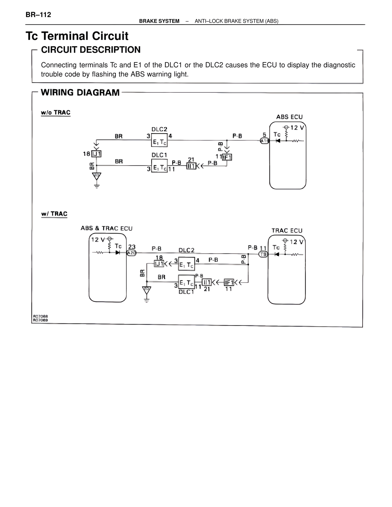
Connecting terminals Tc and E1 of the DLC1 or the DLC2 causes the ECU to display the diagnostic
trouble code by flashing the ABS warning light.
WIRING DIAGRAM
w/o TRAC
ABS ECU
12 V
Tc
DLC2
BR 3 4
E1 Tc
P-B 5
A13
18 IJ1
BR DLC1
P-B 21 11 IF1 P-B
BR
3 E1 Tc 11 II1
P-B
w/ TRAC
ABS & TRAC ECU TRAC ECU
12 V
Tc 23 P-B DLC2 P-B 11 Tc 12 V
A20 18 3 4 P-B T9
IJ1 E1 Tc
BR
BR
3 E1 Tc P-B II1 IF1
3 DLC1 21 11
R07068
R07069