100%
BR–114
BRAKE SYSTEM – ANTI–LOCK BRAKE SYSTEM (ABS)
Ts Terminal Circuit
CIRCUIT DESCRIPTION
The sensor check circuit detects abnormalities in the speed sensor signal which cannot be detected with the diagnostic trouble code check.
Connecting terminals Ts and E1 of the DLC1 in the engine compartment starts the check.
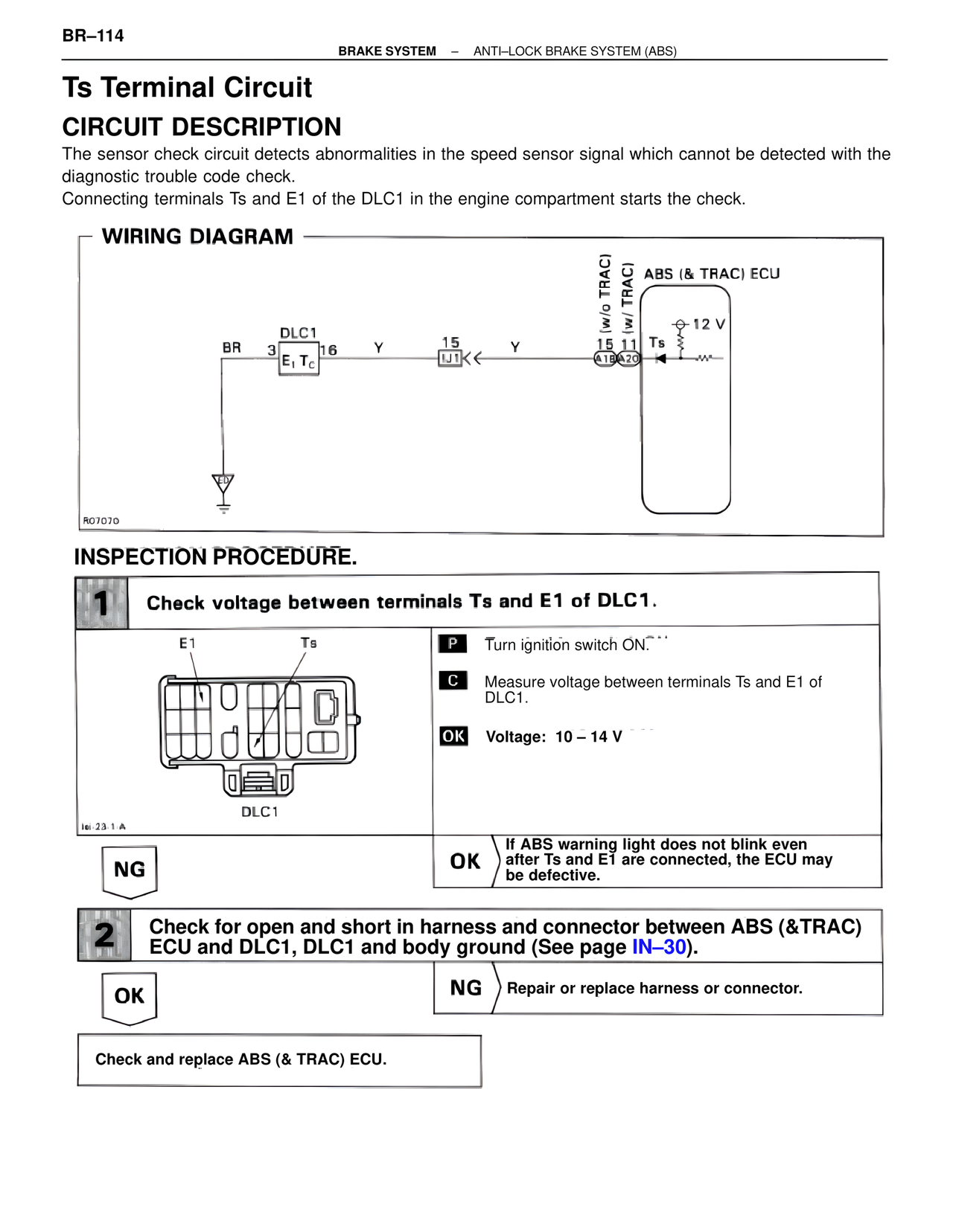
WIRING DIAGRAM
BR 3 DLC1 16 Y 15 Y
E1 Tc
IJ1
(w/o TRAC)
(w/ TRAC)
ABS (& TRAC) ECU
12 V
15 11 Ts
A18 A20
R0707D
INSPECTION PROCEDURE.
1 Check voltage between terminals Ts and E1 of DLC1.
E1 Ts
DLC1
Iei-23-1-A
P Turn ignition switch ON
C Measure voltage between terminals Ts and E1 of DLC1.
OK Voltage: 10 – 14 V
NG
OK If ABS warning light does not blink even after Ts and E1 are connected, the ECU may be defective.
2 Check for open and short in harness and connector between ABS (&TRAC) ECU and DLC1, DLC1 and body ground (See page IN–30).
OK
NG Repair or replace harness or connector.
Check and replace ABS (& TRAC) ECU.