100%
BR–138
BRAKE SYSTEM – TRACTION CONTROL SYSTEM (TRAC)
DTC 31 32 33 34 Speed Sensor Circuit
CIRCUIT DESCRIPTION
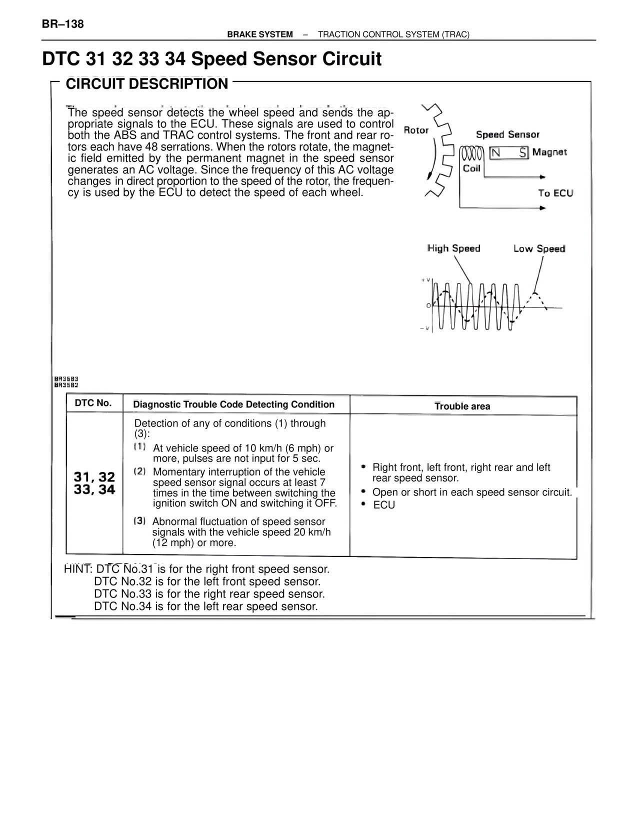
The speed sensor detects the wheel speed and sends the ap-
propriate signals to the ECU. These signals are used to control
both the ABS and TRAC control systems. The front and rear ro-
tors each have 48 serrations. When the rotors rotate, the magnet-
ic field emitted by the permanent magnet in the speed sensor
generates an AC voltage. Since the frequency of this AC voltage
changes in direct proportion to the speed of the rotor, the frequen-
cy is used by the ECU to detect the speed of each wheel.
Rotor Speed Sensor
N S Magnet
Coil
To ECU
High Speed Low Speed
BR3583
BR3582
DTC No. Diagnostic Trouble Code Detecting Condition Trouble area
31, 32
33, 34
Detection of any of conditions (1) through (3):
(1) At vehicle speed of 10 km/h (6 mph) or
more, pulses are not input for 5 sec.
(2) Momentary interruption of the vehicle
speed sensor signal occurs at least 7
times in the time between switching the
ignition switch ON and switching it OFF.
(3) Abnormal fluctuation of speed sensor
signals with the vehicle speed 20 km/h
(12 mph) or more.
• Right front, left front, right rear and left
rear speed sensor.
• Open or short in each speed sensor circuit.
• ECU
HINT: DTC No.31 is for the right front speed sensor.
DTC No.32 is for the left front speed sensor.
DTC No.33 is for the right rear speed sensor.
DTC No.34 is for the left rear speed sensor.