100%
BR–152
BRAKE SYSTEM – TRACTION CONTROL SYSTEM (TRAC)
DTC 47 48 Sub–Throttle Position Sensor Circuit
CIRCUIT DESCRIPTION
This sensor detects the opening angle of the sub–throttle valve and sends the appropriate signals to the ECU.
If a trouble signal is input, the ECU prohibits TRAC control.
DTC No. | Diagnostic Trouble Code Detecting Condition | Trouble area
47
When any of the following (1) through (3) is detected:
(1) Deviation of 5 steps or more to the closed side of the idle step during sub–throttle initial check.
(2) Voltage at terminal IDL2 does not become 0 V even after sub–throttle is driven to fully closed position during sub–throttle initial check.
(3) Voltage at terminal VTA2 of ECM is 1.5 V or more for at least 0.31 sec. while CTP switch is ON.
Sub–throttle position sensor
Open or short in IDL2 circuit
ECM
TRAC ECU
48
Either of the following (1) or (2) continues for at least 0.26 sec.:
(1) Input voltage of ECM terminal VTA2: 4.9 V or more
(2) Input voltage of ECM terminal VTA2: 0.1 V or less.
Sub–throttle position sensor
Open or short in VTA2 circuit
ECM
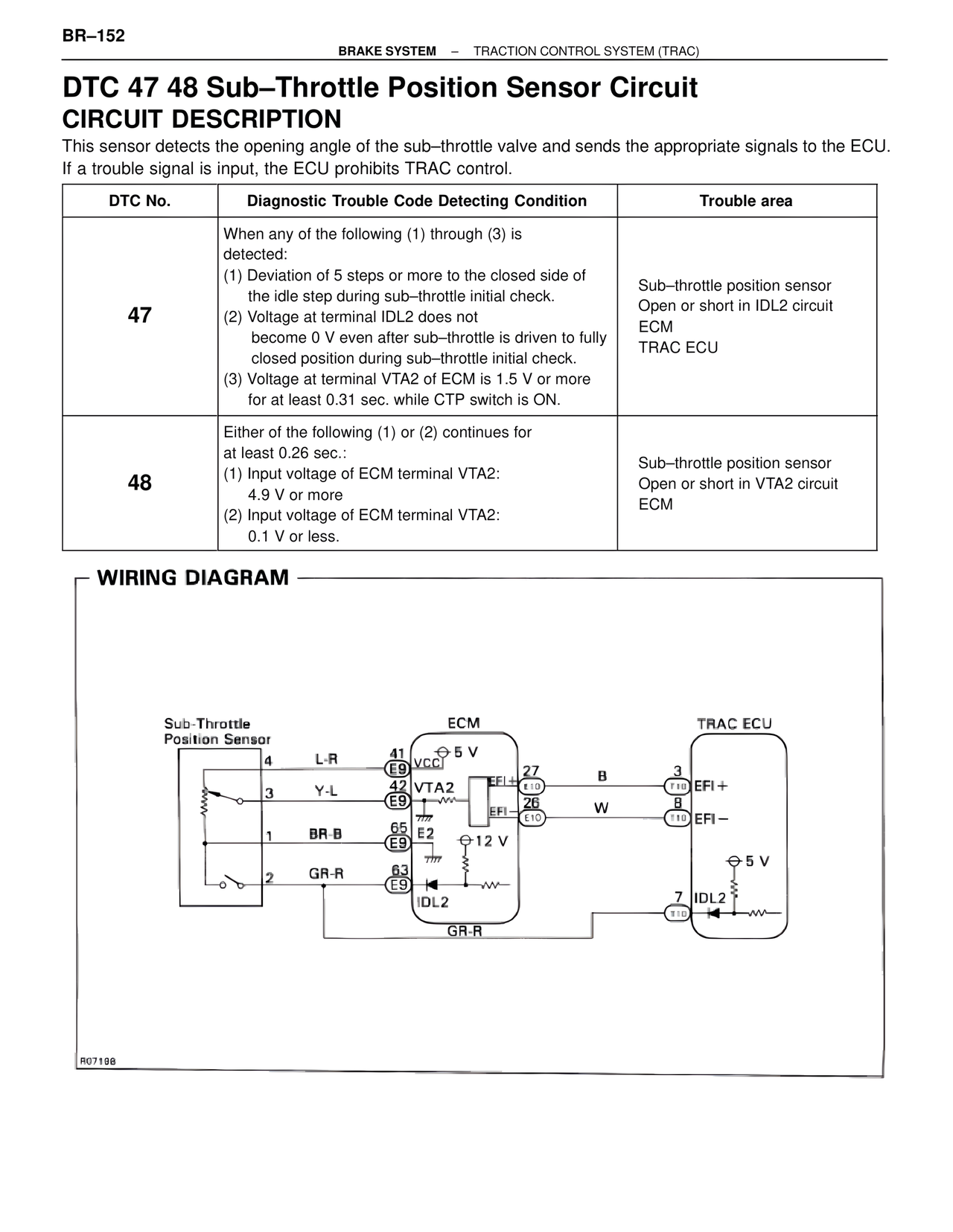
WIRING DIAGRAM
Sub-Throttle Position Sensor
4 L-R
3 Y-L
1 BR-B
2 GR-R
ECM
41 E9 VCC1 ⊕ 5 V
42 E9 VTA2
EFI+ 27 B
EFI- 26 W
65 E9 E2 ⊕ 12 V
63 E9 IDL2
GR-R
TRAC ECU
3 T10 EFI+
8 T10 EFI-
⊕ 5 V
7 IDL2
T10
R07198