Page text (OCR transcript)
BR–73
BRAKE SYSTEM – ANTI–LOCK BRAKE SYSTEM (ABS)

INSPECTION PROCEDURE (w/o TRAC)

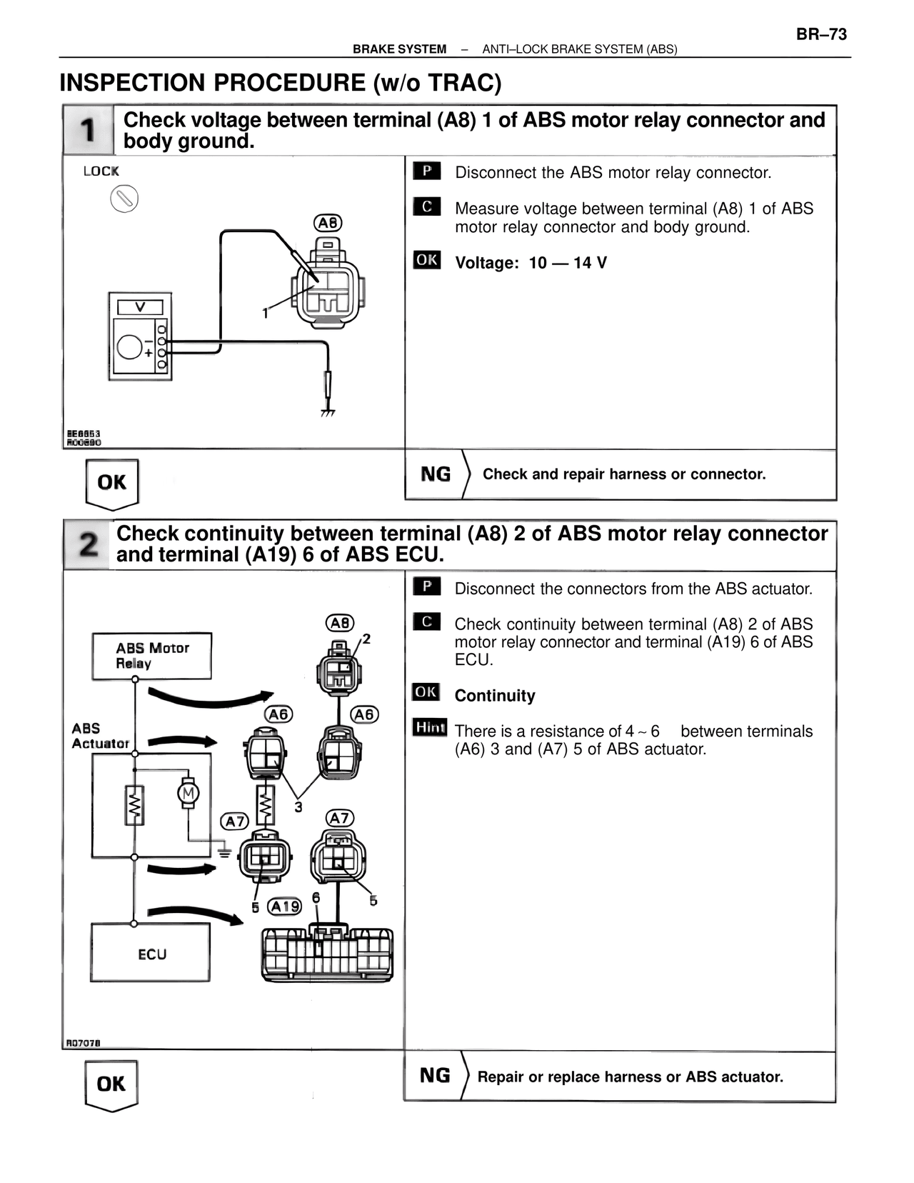
1  Check voltage between terminal (A8) 1 of ABS motor relay connector and body ground.

LOCK

P  Disconnect the ABS motor relay connector.

C  Measure voltage between terminal (A8) 1 of ABS motor relay connector and body ground.

OK  Voltage: 10 — 14 V

BE6853
ROC890

OK

NG  Check and repair harness or connector.

2  Check continuity between terminal (A8) 2 of ABS motor relay connector and terminal (A19) 6 of ABS ECU.

P  Disconnect the connectors from the ABS actuator.

C  Check continuity between terminal (A8) 2 of ABS motor relay connector and terminal (A19) 6 of ABS ECU.

OK  Continuity

Hint  There is a resistance of 4 ~ 6    between terminals (A6) 3 and (A7) 5 of ABS actuator.

ABS Motor Relay

A8
A6
A6

ABS Actuator

A7
A7

A19

ECU

R07078

OK

NG  Repair or replace harness or ABS actuator.