100%
BE–134
BODY ELECTRICAL SYSTEM – THEFT DETERRENT AND DOOR LOCK CONTROL SYSTEM
Theft Deterrent Horn Circuit
CIRCUIT DESCRIPTION
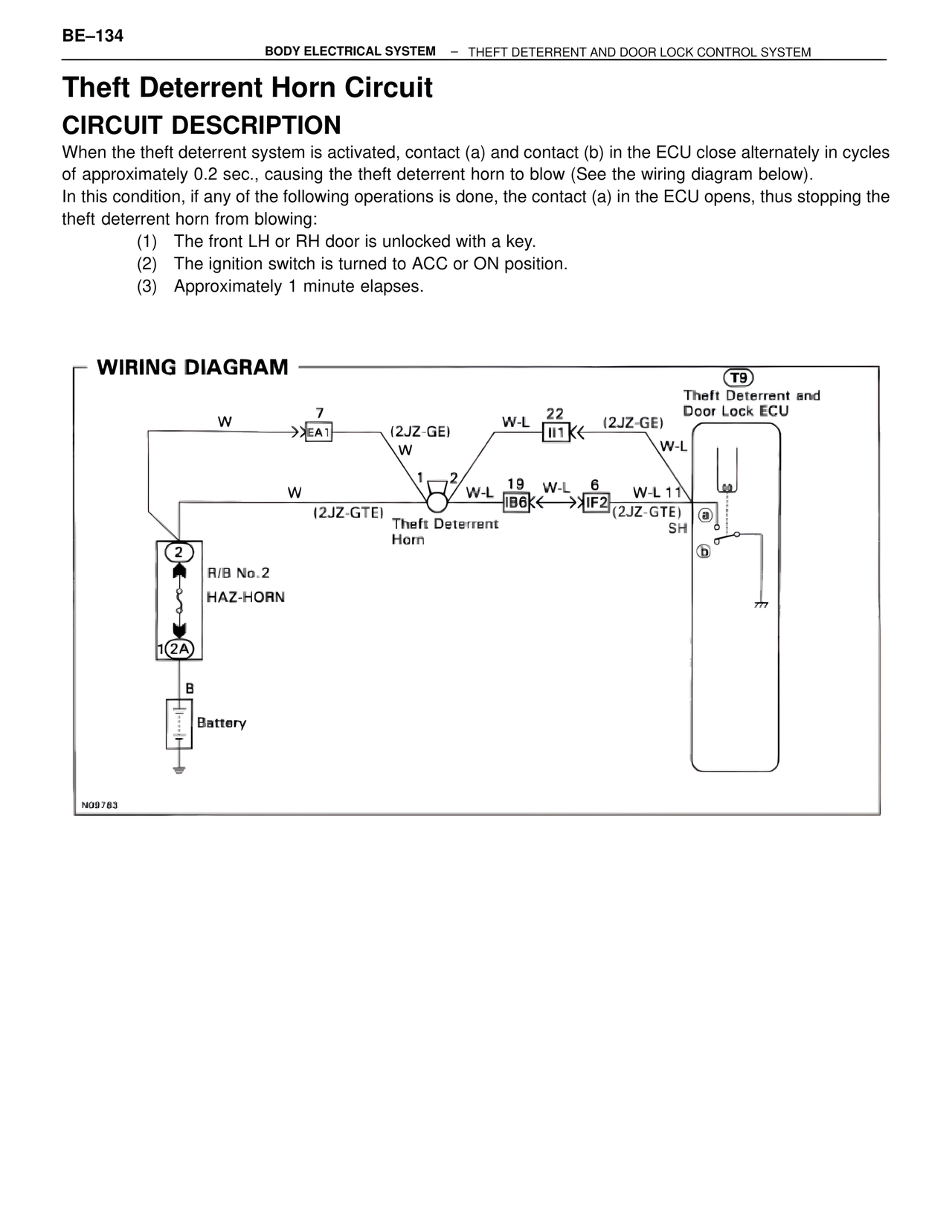
When the theft deterrent system is activated, contact (a) and contact (b) in the ECU close alternately in cycles of approximately 0.2 sec., causing the theft deterrent horn to blow (See the wiring diagram below).
In this condition, if any of the following operations is done, the contact (a) in the ECU opens, thus stopping the theft deterrent horn from blowing:
(1) The front LH or RH door is unlocked with a key.
(2) The ignition switch is turned to ACC or ON position.
(3) Approximately 1 minute elapses.
WIRING DIAGRAM
T9
Theft Deterrent and
Door Lock ECU
W 7
>>EA1 (2JZ-GE)
W
W-L 22
II1< (2JZ-GE)
W-L
W 1 2
(2JZ-GTE) W-L
Theft Deterrent
Horn
19 W-L 6 W-L 11
IB6< >>IF2 (2JZ-GTE)
SH
(a)
(b)
2
R/B No.2
HAZ-HORN
1 2A
B
Battery
N09783