100%
Page text (OCR transcript)
BE–145
BODY ELECTRICAL SYSTEM – THEFT DETERRENT AND DOOR LOCK CONTROL SYSTEM

Door Unlock Detection Switch Circuit

CIRCUIT DESCRIPTION
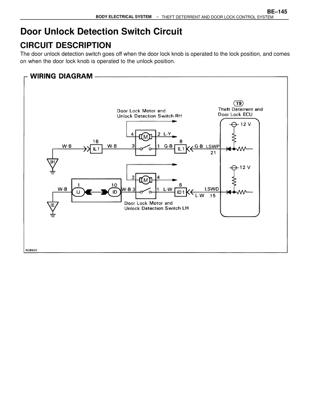
The door unlock detection switch goes off when the door lock knob is operated to the lock position, and comes
on when the door lock knob is operated to the unlock position.

WIRING DIAGRAM

Door Lock Motor and
Unlock Detection Switch RH

4  M  2 L-Y

W-B  16        W-B  3  o  o  1 G-B  8
         IL1                        IL1  G-B LSWP
                                              21
IH

2  M  4

W-B  1        10        W-B 3  o  o  1 L-W  6
         IJ        ID                    ID1  LSWD
                                              L-W  15
IE

Door Lock Motor and
Unlock Detection Switch LH

T9
Theft Deterrent and
Door Lock ECU

12 V

12 V

N0B665