100%
BE–172
BODY ELECTRICAL SYSTEM – CRUISE CONTROL SYSTEM
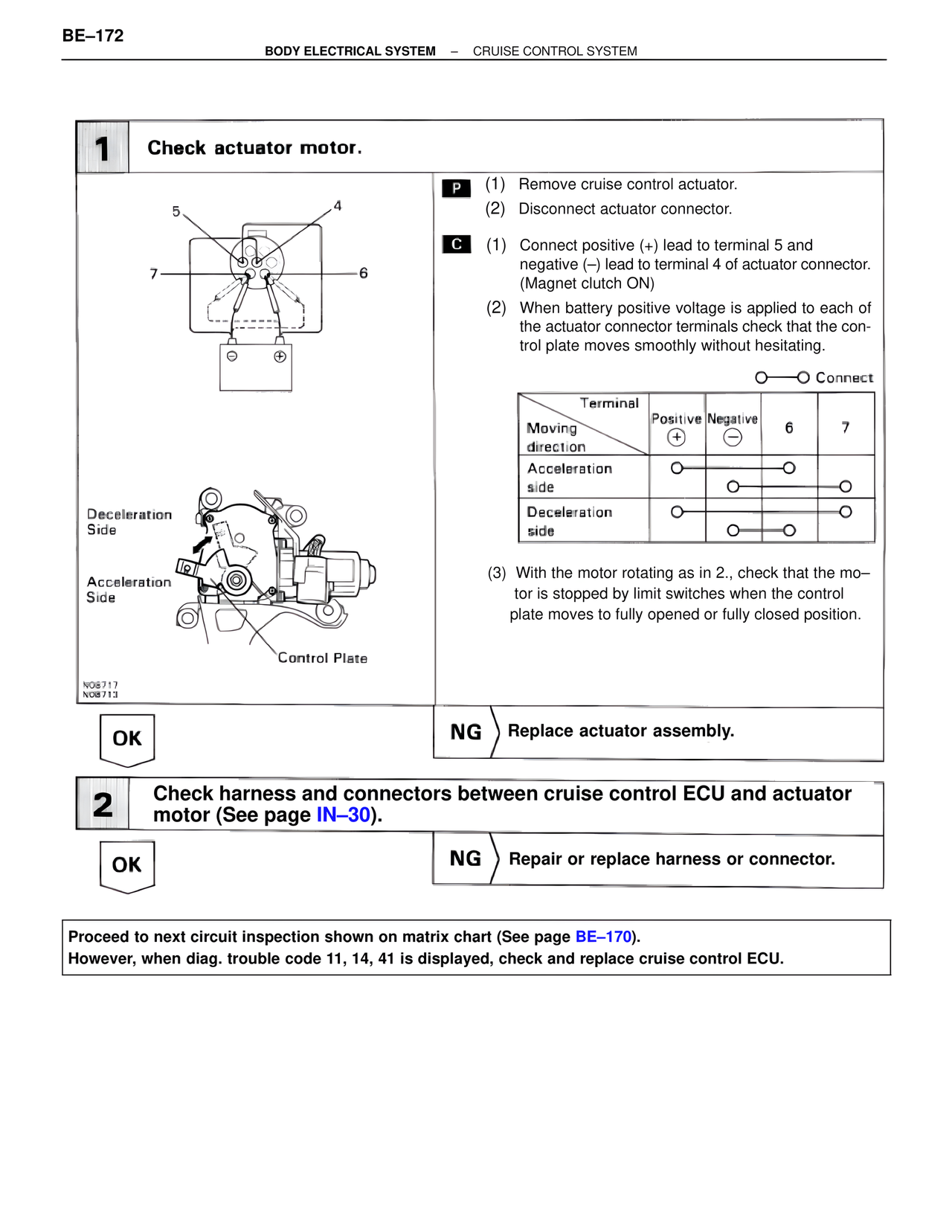
1 Check actuator motor.
5 4
7 6
Deceleration
Side
Acceleration
Side
Control Plate
N08717
N08713
P (1) Remove cruise control actuator.
(2) Disconnect actuator connector.
C (1) Connect positive (+) lead to terminal 5 and
negative (–) lead to terminal 4 of actuator connector.
(Magnet clutch ON)
(2) When battery positive voltage is applied to each of
the actuator connector terminals check that the con-
trol plate moves smoothly without hesitating.
O——O Connect
Terminal
Moving Positive Negative 6 7
direction (+) (–)
Acceleration O O
side O O
Deceleration O O
side O——O
(3) With the motor rotating as in 2., check that the mo–
tor is stopped by limit switches when the control
plate moves to fully opened or fully closed position.
OK NG Replace actuator assembly.
2 Check harness and connectors between cruise control ECU and actuator
motor (See page IN–30).
OK NG Repair or replace harness or connector.
Proceed to next circuit inspection shown on matrix chart (See page BE–170).
However, when diag. trouble code 11, 14, 41 is displayed, check and replace cruise control ECU.