100%
BE–182
BODY ELECTRICAL SYSTEM – CRUISE CONTROL SYSTEM
Stop Light Switch Circuit
CIRCUIT DESCRIPTION
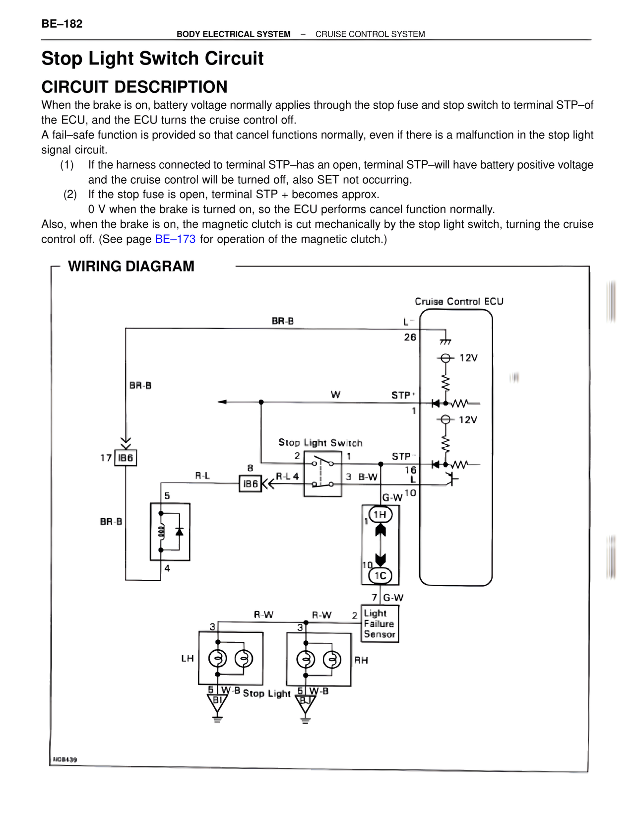
When the brake is on, battery voltage normally applies through the stop fuse and stop switch to terminal STP–of
the ECU, and the ECU turns the cruise control off.
A fail–safe function is provided so that cancel functions normally, even if there is a malfunction in the stop light
signal circuit.
(1) If the harness connected to terminal STP–has an open, terminal STP–will have battery positive voltage
and the cruise control will be turned off, also SET not occurring.
(2) If the stop fuse is open, terminal STP + becomes approx.
0 V when the brake is turned on, so the ECU performs cancel function normally.
Also, when the brake is on, the magnetic clutch is cut mechanically by the stop light switch, turning the cruise
control off. (See page BE–173 for operation of the magnetic clutch.)
WIRING DIAGRAM
Cruise Control ECU
BR-B
L-
26
12V
BR-B
W
STP+
1
12V
Stop Light Switch
2 1
STP-
17 IB6
8
R-L 4
3 B-W
16
R-L
IB6
L
G-W 10
5
1H
BR-B
10
1C
4
7 G-W
R-W
R-W
2
Light
3
3
Failure
Sensor
LH
RH
5 W-B Stop Light 5 W-B
NG8439