100%
BE–190
BODY ELECTRICAL SYSTEM – CRUISE CONTROL SYSTEM
1 Check operation of brake warning light.
C Check that the brake warning light in the instrument panel comes on when the parking brake lever is
pulled up with the engine running, and the light goes off when the parking brake lever is released.
OK
NG Check brake warning light circuit
(See page BE–42).
2 Input signal check.
C (1) See input signal check on page BE–169.
(2) Check the indicator light when the parking brake
lever is pulled up.
Parking brake lever
is pulled up
ON
OFF
BE4006
OK The indicator light goes off when the parking brake lever
is pulled up.
NG
OK Proceed to next circuit inspection shown on matrix
chart (See page BE–170).
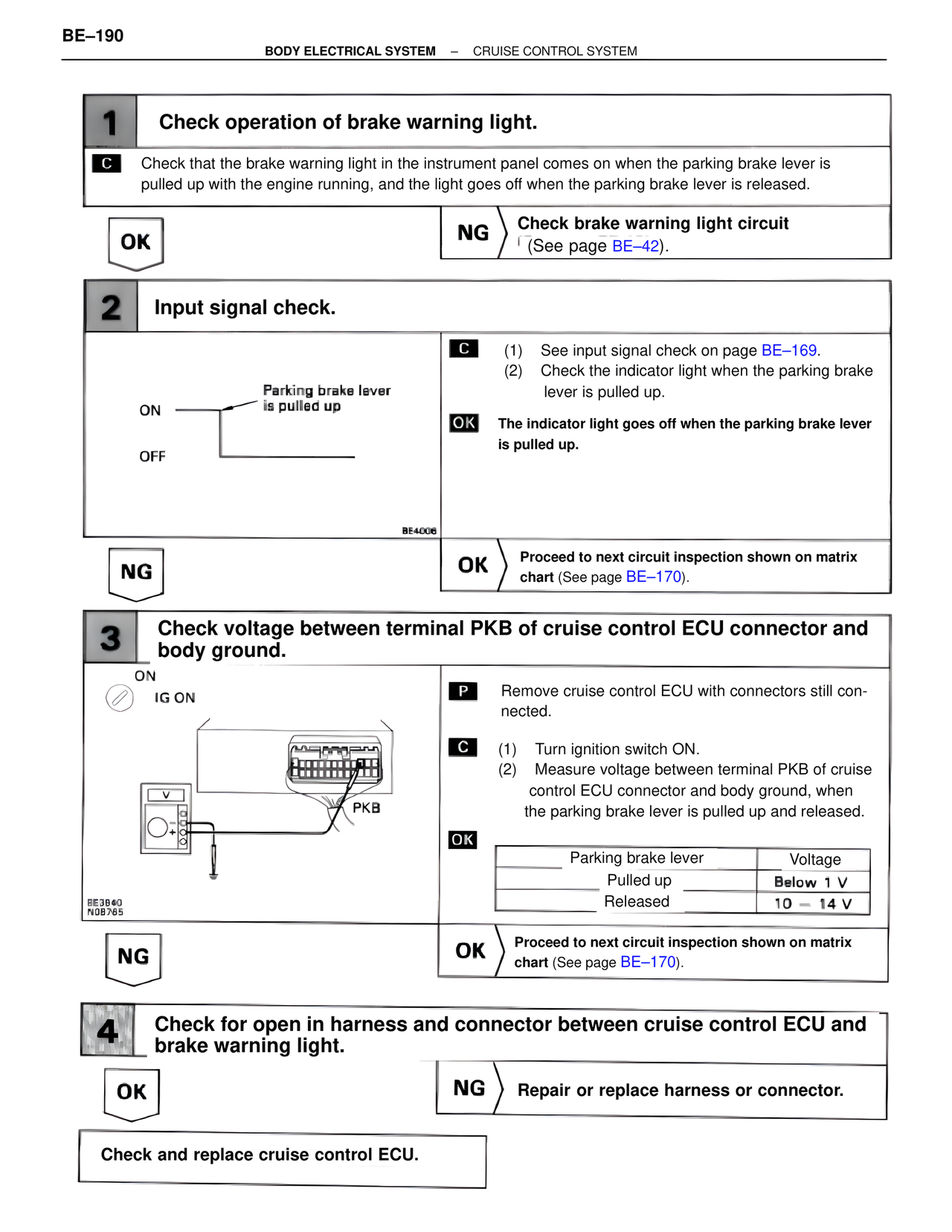
3 Check voltage between terminal PKB of cruise control ECU connector and
body ground.
ON
IG ON
BE3640
N0B765
PKB
P Remove cruise control ECU with connectors still con-
nected.
C (1) Turn ignition switch ON.
(2) Measure voltage between terminal PKB of cruise
control ECU connector and body ground, when
the parking brake lever is pulled up and released.
OK
Parking brake lever Voltage
Pulled up Below 1 V
Released 10 – 14 V
NG
OK Proceed to next circuit inspection shown on matrix
chart (See page BE–170).
4 Check for open in harness and connector between cruise control ECU and
brake warning light.
OK
NG Repair or replace harness or connector.
Check and replace cruise control ECU.