100%
BODY ELECTRICAL SYSTEM – WIPER AND WASHER SYSTEM
BE–37
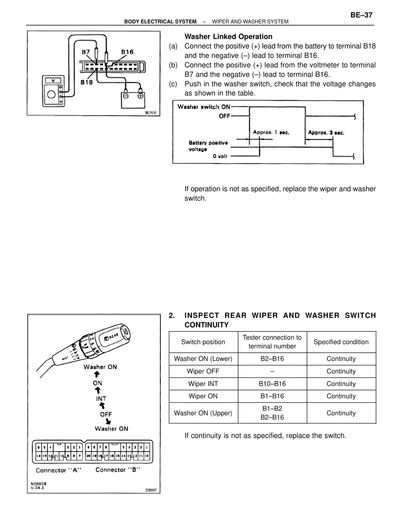
Washer Linked Operation
(a) Connect the positive (+) lead from the battery to terminal B18
and the negative (–) lead to terminal B16.
(b) Connect the positive (+) lead from the voltmeter to terminal
B7 and the negative (–) lead to terminal B16.
(c) Push in the washer switch, check that the voltage changes
as shown in the table.
Washer switch ON
OFF
Approx. 1 sec.
Approx. 3 sec.
Battery positive
voltage
0 volt
If operation is not as specified, replace the wiper and washer
switch.
2. INSPECT REAR WIPER AND WASHER SWITCH
CONTINUITY
Switch position | Tester connection to terminal number | Specified condition
Washer ON (Lower) | B2–B16 | Continuity
Wiper OFF | – | Continuity
Wiper INT | B10–B16 | Continuity
Wiper ON | B1–B16 | Continuity
Washer ON (Upper) | B1–B2
B2–B16 | Continuity
If continuity is not as specified, replace the switch.
Washer ON
ON
INT
OFF
Washer ON
Connector ''A''
Connector ''B''
N0885B
V-34-2
209287
BE0930