100%
BE–46
BODY ELECTRICAL SYSTEM – COMBINATION METER
SPEEDOMETER INSPECTION
ON–VEHICLE
Using a speedometer tester, inspect the speedometer for allowable indication error and check the operation of the odometer.
HINT: Tire wear and tire over or under inflation will increase the indication error.
If error is excessive, replace the speedometer.
USA (mph)
Standard indication Allowable range
20 18–24
40 38–44
60 56–66
80 78–88
100 98–110
120 118–132
CANADA (km/h)
Standard indication Allowable range
20 17–24
40 38–46
60 57.5–67
80 77–88
100 96–109
120 115–130
140 134–151.5
160 153–173
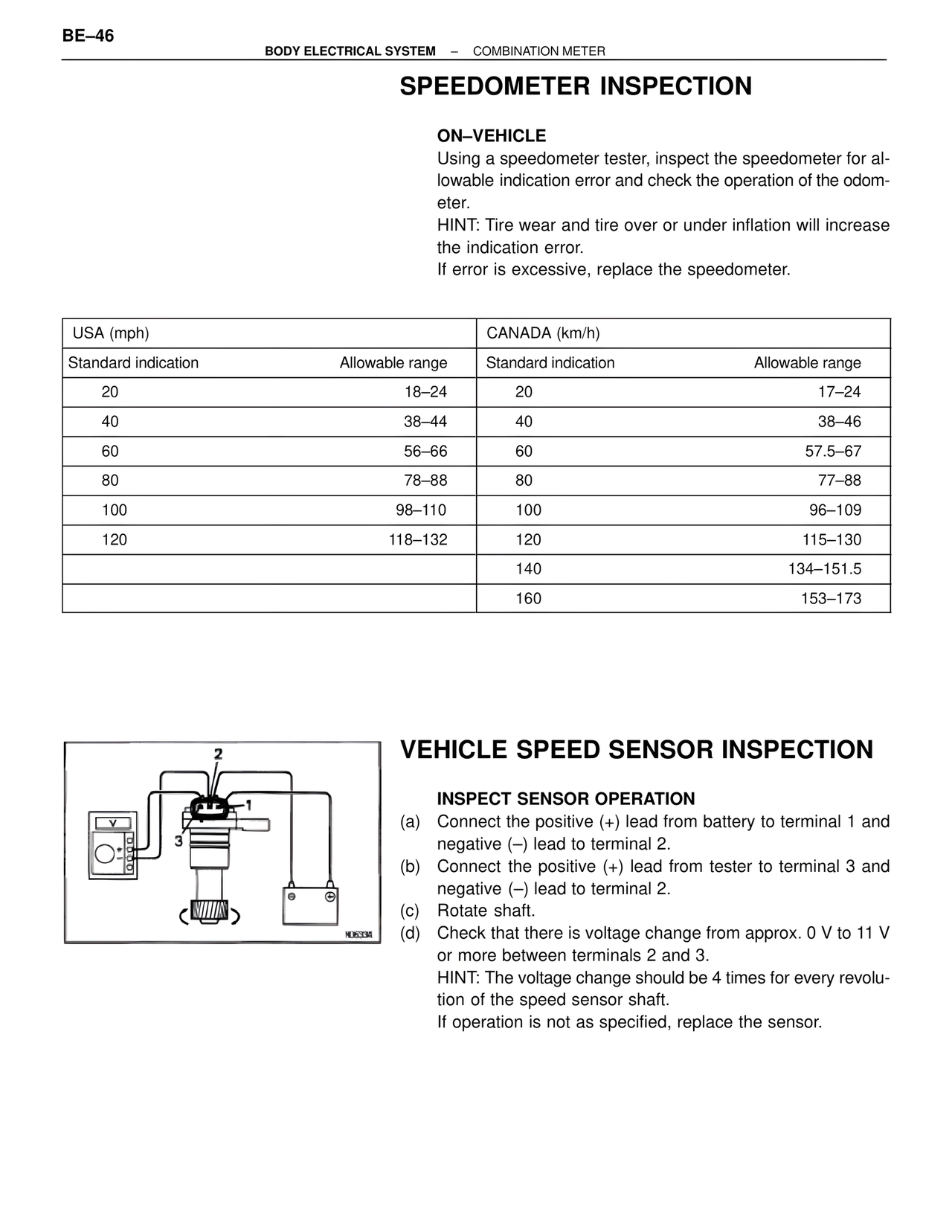
VEHICLE SPEED SENSOR INSPECTION
INSPECT SENSOR OPERATION
(a) Connect the positive (+) lead from battery to terminal 1 and negative (–) lead to terminal 2.
(b) Connect the positive (+) lead from tester to terminal 3 and negative (–) lead to terminal 2.
(c) Rotate shaft.
(d) Check that there is voltage change from approx. 0 V to 11 V or more between terminals 2 and 3.
HINT: The voltage change should be 4 times for every revolution of the speed sensor shaft.
If operation is not as specified, replace the sensor.
H06334