100%
BE-50
BODY ELECTRICAL SYSTEM – COMBINATION METER
Engine Coolant Temperature Gauge
Ignition Switch
Sender Gauge
Battery
BE1219
Z07423
Engine Coolant Temperature Gauge
Test Bulb (3W)
Battery
BE0144
214747
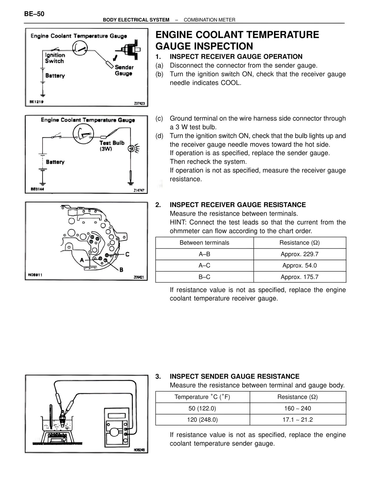
A
C
B
N08911
209421
ENGINE COOLANT TEMPERATURE GAUGE INSPECTION
1. INSPECT RECEIVER GAUGE OPERATION
(a) Disconnect the connector from the sender gauge.
(b) Turn the ignition switch ON, check that the receiver gauge needle indicates COOL.
(c) Ground terminal on the wire harness side connector through a 3 W test bulb.
(d) Turn the ignition switch ON, check that the bulb lights up and the receiver gauge needle moves toward the hot side.
If operation is as specified, replace the sender gauge.
Then recheck the system.
If operation is not as specified, measure the receiver gauge resistance.
2. INSPECT RECEIVER GAUGE RESISTANCE
Measure the resistance between terminals.
HINT: Connect the test leads so that the current from the ohmmeter can flow according to the chart order.
Between terminals | Resistance (Ω)
A–B | Approx. 229.7
A–C | Approx. 54.0
B–C | Approx. 175.7
If resistance value is not as specified, replace the engine coolant temperature receiver gauge.
3. INSPECT SENDER GAUGE RESISTANCE
Measure the resistance between terminal and gauge body.
Temperature °C (°F) | Resistance (Ω)
50 (122.0) | 160 ~ 240
120 (248.0) | 17.1 ~ 21.2
If resistance value is not as specified, replace the engine coolant temperature sender gauge.
H06248