Page text (OCR transcript)
BODY ELECTRICAL SYSTEM – DEFOGGER SYSTEM

BE–65

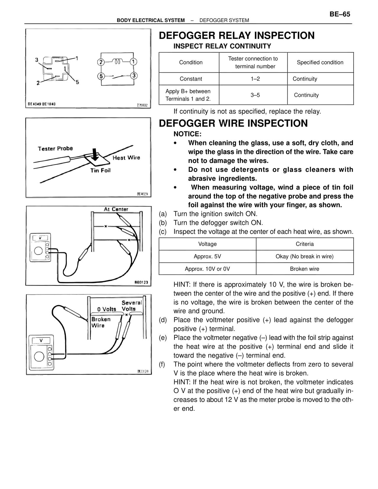
DEFOGGER RELAY INSPECTION

INSPECT RELAY CONTINUITY

Condition | Tester connection to terminal number | Specified condition
Constant | 1–2 | Continuity
Apply B+ between Terminals 1 and 2. | 3–5 | Continuity

If continuity is not as specified, replace the relay.

DEFOGGER WIRE INSPECTION

NOTICE:
• When cleaning the glass, use a soft, dry cloth, and wipe the glass in the direction of the wire. Take care not to damage the wires.
• Do not use detergents or glass cleaners with abrasive ingredients.
• When measuring voltage, wind a piece of tin foil around the top of the negative probe and press the foil against the wire with your finger, as shown.

(a) Turn the ignition switch ON.
(b) Turn the defogger switch ON.
(c) Inspect the voltage at the center of each heat wire, as shown.

Voltage | Criteria
Approx. 5V | Okay (No break in wire)
Approx. 10V or 0V | Broken wire

HINT: If there is approximately 10 V, the wire is broken between the center of the wire and the positive (+) end. If there is no voltage, the wire is broken between the center of the wire and ground.

(d) Place the voltmeter positive (+) lead against the defogger positive (+) terminal.
(e) Place the voltmeter negative (–) lead with the foil strip against the heat wire at the positive (+) terminal end and slide it toward the negative (–) terminal end.
(f) The point where the voltmeter deflects from zero to several V is the place where the heat wire is broken.
HINT: If the heat wire is not broken, the voltmeter indicates O V at the positive (+) end of the heat wire but gradually increases to about 12 V as the meter probe is moved to the other end.

Tester Probe
Heat Wire
Tin Foil

At Center

0 Volts | Several Volts
Broken Wire

BE4049 BE1840
BE0029
BE0129
BE0129