100%
BODY ELECTRICAL SYSTEM – POWER WINDOW CONTROL SYSTEM
BE–69
POWER WINDOW MASTER SWITCH INSPECTION
1. INSPECT SWITCH CONTINUITY
Driver's Switch
Switch position | Tester connection to terminal number | Specified condition
UP | 4–10
8–9 | Continuity
OFF | 8–10
8–9 | Continuity
DOWN | 4–9
8–10 | Continuity
Passenger's Switch (Window unlock)
Switch position | Tester connection to terminal number | Specified condition
UP | 4–5
7–8 | Continuity
OFF | 5–8
7–8 | Continuity
DOWN | 4–7
5–8 | Continuity
Passenger's Switch (Window lock)
Switch position' | Tester connection to terminal number | Specified condition
UP | 4–5 | Continuity
OFF | 5–7 | Continuity
DOWN | 4–7 | Continuity
If continuity is not as specified, replace the switch.
NO8853
*10-2
209149
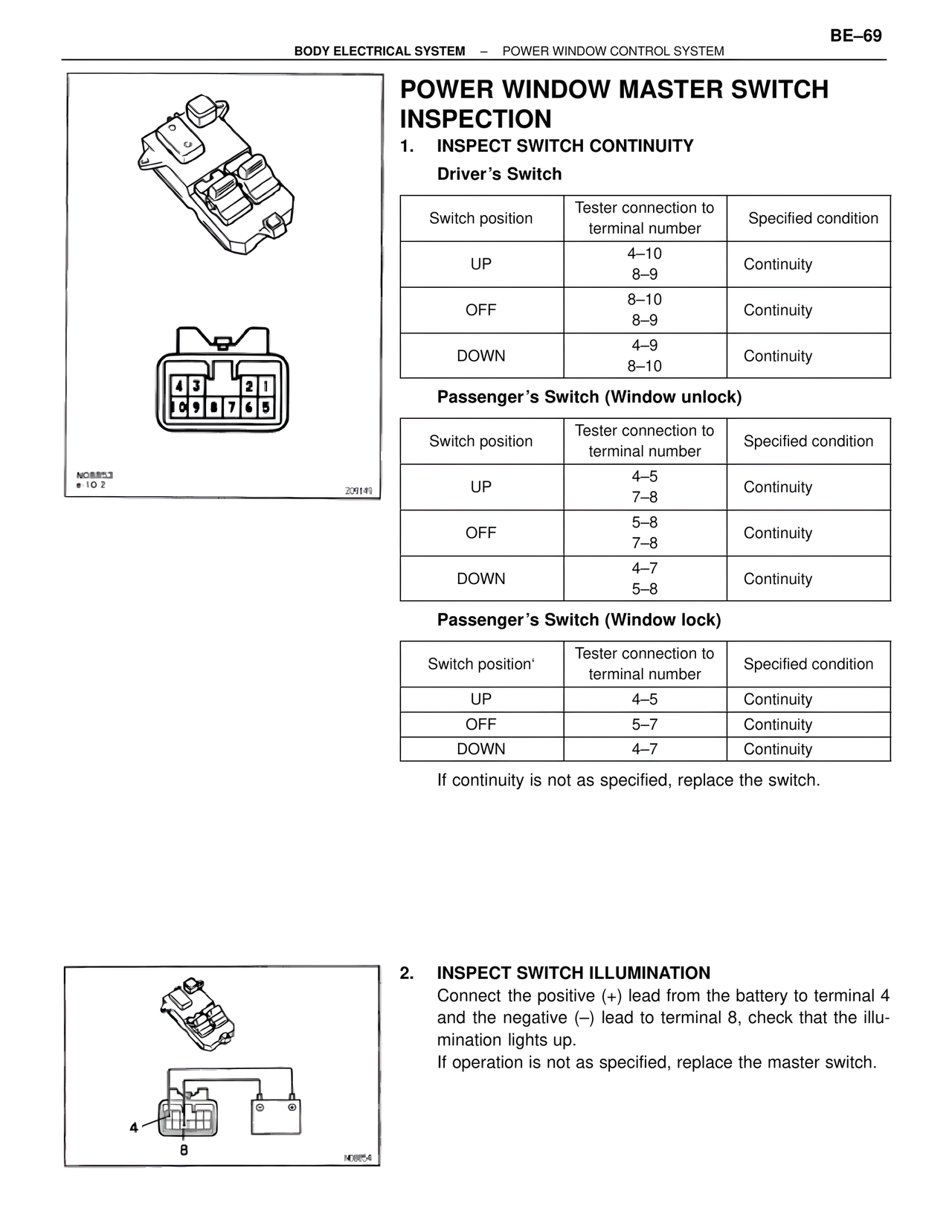
2. INSPECT SWITCH ILLUMINATION
Connect the positive (+) lead from the battery to terminal 4
and the negative (–) lead to terminal 8, check that the illumination lights up.
If operation is not as specified, replace the master switch.
4
8
NO8854