Page text (OCR transcript)
CH–11

CHARGING SYSTEM – GENERATOR

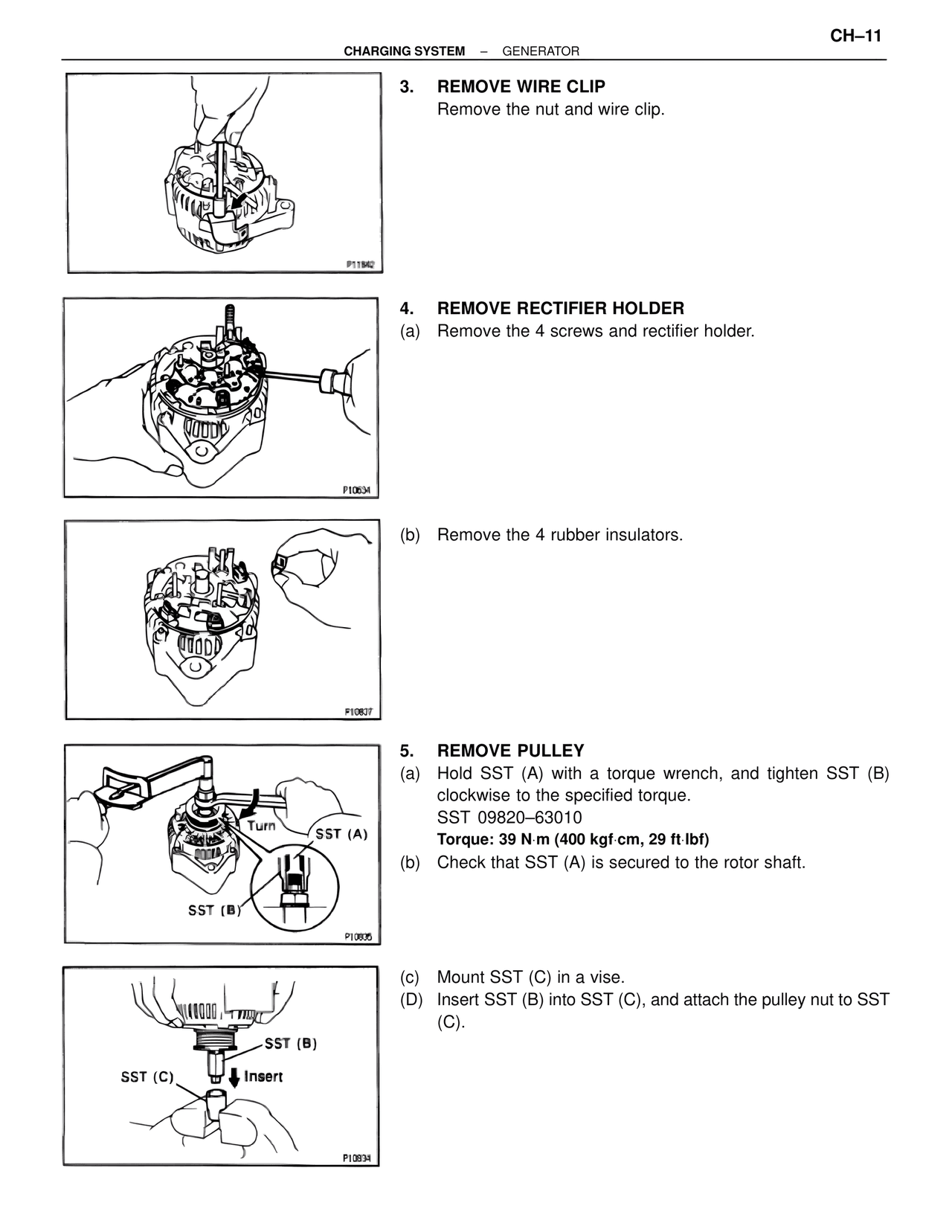
3. REMOVE WIRE CLIP
Remove the nut and wire clip.

4. REMOVE RECTIFIER HOLDER
(a) Remove the 4 screws and rectifier holder.

(b) Remove the 4 rubber insulators.

5. REMOVE PULLEY
(a) Hold SST (A) with a torque wrench, and tighten SST (B) clockwise to the specified torque.
SST 09820–63010
Torque: 39 N·m (400 kgf·cm, 29 ft·lbf)
(b) Check that SST (A) is secured to the rotor shaft.

(c) Mount SST (C) in a vise.
(D) Insert SST (B) into SST (C), and attach the pulley nut to SST (C).

Turn
SST (A)
SST (B)

SST (B)
SST (C)
Insert

P11842
P10634
P10807
P10805
P10934