100%
DI-2 BODY DIMENSIONS
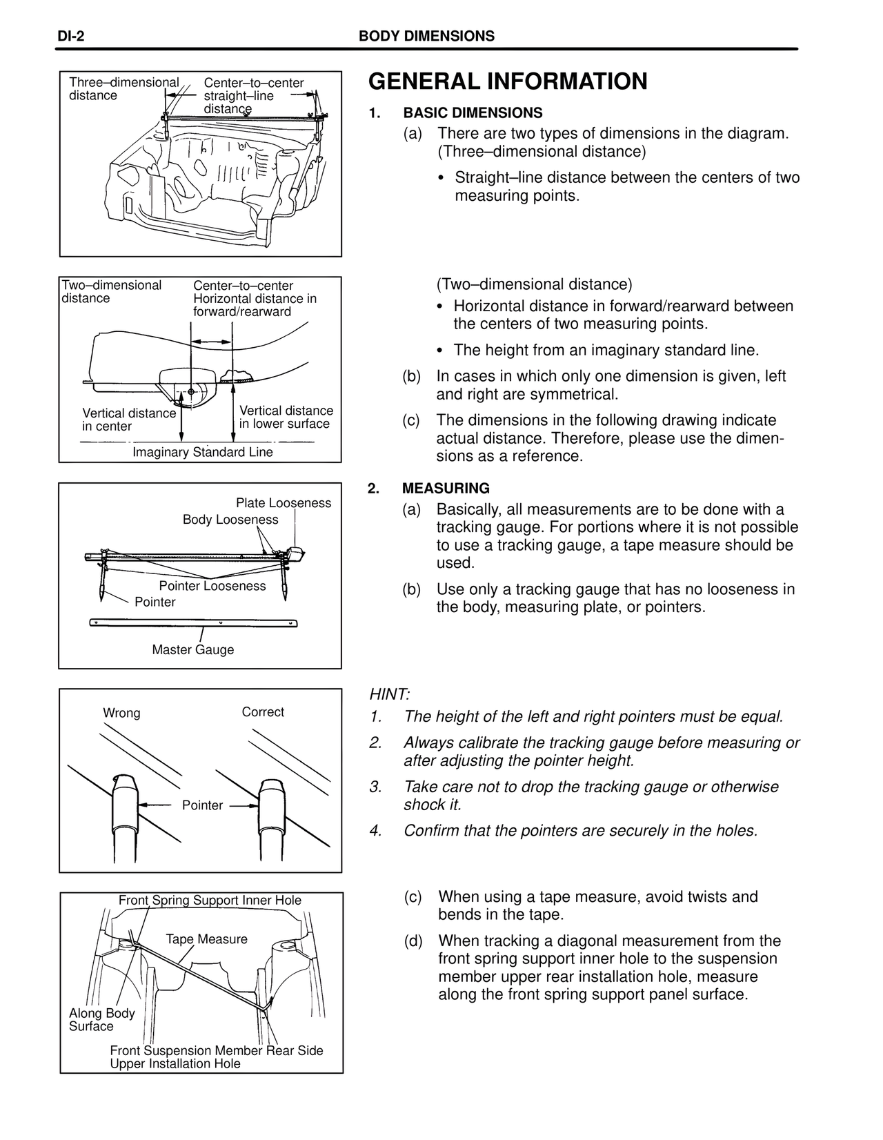
Three–dimensional distance Center–to–center straight–line distance
Two–dimensional distance Center–to–center Horizontal distance in forward/rearward
Vertical distance in center Vertical distance in lower surface
Imaginary Standard Line
Plate Looseness
Body Looseness
Pointer Looseness
Pointer
Master Gauge
Wrong Correct
Pointer
Front Spring Support Inner Hole
Tape Measure
Along Body Surface
Front Suspension Member Rear Side Upper Installation Hole
GENERAL INFORMATION
1. BASIC DIMENSIONS
(a) There are two types of dimensions in the diagram.
(Three–dimensional distance)
• Straight–line distance between the centers of two measuring points.
(Two–dimensional distance)
• Horizontal distance in forward/rearward between the centers of two measuring points.
• The height from an imaginary standard line.
(b) In cases in which only one dimension is given, left and right are symmetrical.
(c) The dimensions in the following drawing indicate actual distance. Therefore, please use the dimensions as a reference.
2. MEASURING
(a) Basically, all measurements are to be done with a tracking gauge. For portions where it is not possible to use a tracking gauge, a tape measure should be used.
(b) Use only a tracking gauge that has no looseness in the body, measuring plate, or pointers.
HINT:
1. The height of the left and right pointers must be equal.
2. Always calibrate the tracking gauge before measuring or after adjusting the pointer height.
3. Take care not to drop the tracking gauge or otherwise shock it.
4. Confirm that the pointers are securely in the holes.
(c) When using a tape measure, avoid twists and bends in the tape.
(d) When tracking a diagonal measurement from the front spring support inner hole to the suspension member upper rear installation hole, measure along the front spring support panel surface.