100%
Mark "6"
61.986–61.988 mm (2.44039–2.44047 in.)
Mark "7"
61.984–61.986 mm (2.44031–2.44039 in.)
Bearing center wall thickness:
Mark "1"
1.994–1.997 mm (0.0785–0.0786 in.)
Mark "2"
1.997–2.000 mm (0.0786–0.0787 in.)
Mark "3"
2.000–2.003 mm (0.0787–0.0789 in.)
Mark "4"
2.003–2.006 mm (0.0789–0.0790 in.)
Mark "5"
2.006–2.009 mm (0.0790–0.0791 in.)
Standard sized Bearing Selection chart
Crankshaft number mark | Cylinder block number mark
| 0 | 1 | 2 | 3 | 4 | 5 | 6 | 7
0 | 1 | 1 | 1 | 2 | 2 | 2 | 3 | 3
1 | 1 | 1 | 2 | 2 | 2 | 3 | 3 | 3
2 | 1 | 2 | 2 | 2 | 3 | 3 | 3 | 4
3 | 2 | 2 | 2 | 3 | 3 | 3 | 4 | 4
4 | 2 | 2 | 3 | 3 | 3 | 4 | 4 | 4
5 | 2 | 3 | 3 | 3 | 4 | 4 | 5 | 5
6 | 3 | 3 | 3 | 4 | 4 | 5 | 5 | 5
7 | 3 | 3 | 4 | 4 | 5 | 5 | 5 | 5
EXAMPLE: Cylinder block "3" Crankshaft "4"
= Use bearing "3"
(k) Completely remove the Plastigage.
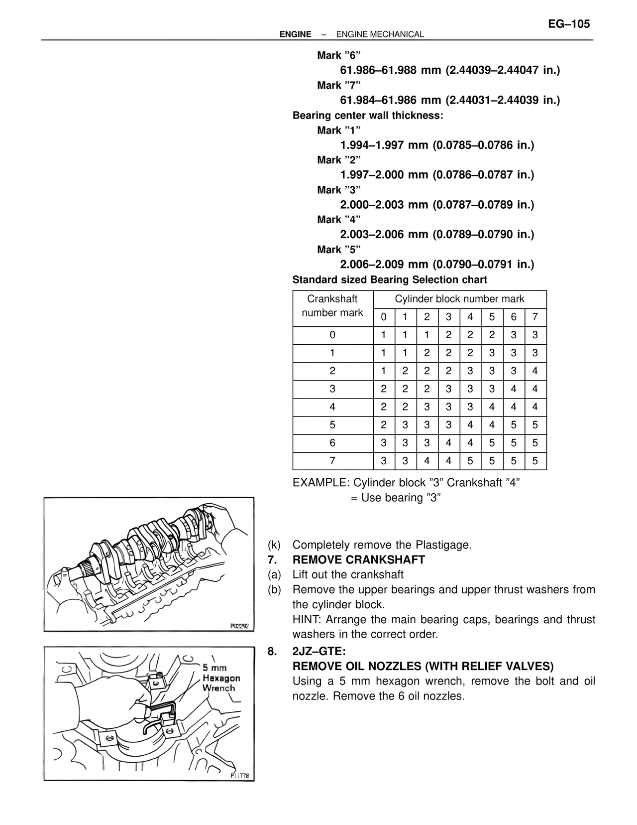
7. REMOVE CRANKSHAFT
(a) Lift out the crankshaft
(b) Remove the upper bearings and upper thrust washers from
the cylinder block.
HINT: Arrange the main bearing caps, bearings and thrust
washers in the correct order.
8. 2JZ–GTE:
REMOVE OIL NOZZLES (WITH RELIEF VALVES)
Using a 5 mm hexagon wrench, remove the bolt and oil
nozzle. Remove the 6 oil nozzles.
5 mm
Hexagon
Wrench
P00292
P11778