100%
EM-52
ENGINE MECHANICAL (2JZ-GTE) - CYLINDER HEAD
P12114
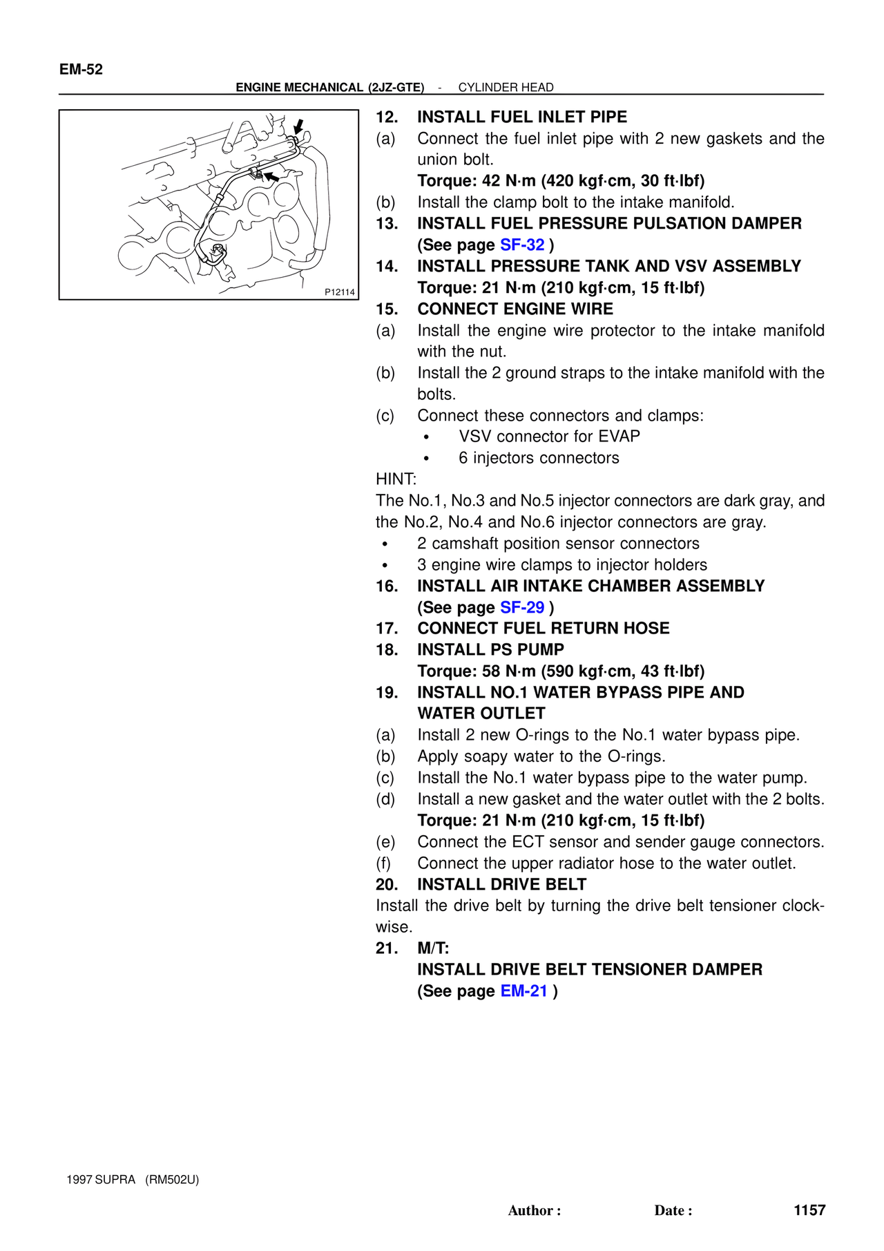
12. INSTALL FUEL INLET PIPE
(a) Connect the fuel inlet pipe with 2 new gaskets and the union bolt.
Torque: 42 N·m (420 kgf·cm, 30 ft·lbf)
(b) Install the clamp bolt to the intake manifold.
13. INSTALL FUEL PRESSURE PULSATION DAMPER
(See page SF-32 )
14. INSTALL PRESSURE TANK AND VSV ASSEMBLY
Torque: 21 N·m (210 kgf·cm, 15 ft·lbf)
15. CONNECT ENGINE WIRE
(a) Install the engine wire protector to the intake manifold with the nut.
(b) Install the 2 ground straps to the intake manifold with the bolts.
(c) Connect these connectors and clamps:
• VSV connector for EVAP
• 6 injectors connectors
HINT:
The No.1, No.3 and No.5 injector connectors are dark gray, and the No.2, No.4 and No.6 injector connectors are gray.
• 2 camshaft position sensor connectors
• 3 engine wire clamps to injector holders
16. INSTALL AIR INTAKE CHAMBER ASSEMBLY
(See page SF-29 )
17. CONNECT FUEL RETURN HOSE
18. INSTALL PS PUMP
Torque: 58 N·m (590 kgf·cm, 43 ft·lbf)
19. INSTALL NO.1 WATER BYPASS PIPE AND WATER OUTLET
(a) Install 2 new O-rings to the No.1 water bypass pipe.
(b) Apply soapy water to the O-rings.
(c) Install the No.1 water bypass pipe to the water pump.
(d) Install a new gasket and the water outlet with the 2 bolts.
Torque: 21 N·m (210 kgf·cm, 15 ft·lbf)
(e) Connect the ECT sensor and sender gauge connectors.
(f) Connect the upper radiator hose to the water outlet.
20. INSTALL DRIVE BELT
Install the drive belt by turning the drive belt tensioner clockwise.
21. M/T:
INSTALL DRIVE BELT TENSIONER DAMPER
(See page EM-21 )
1997 SUPRA (RM502U)
Author : Date : 1157