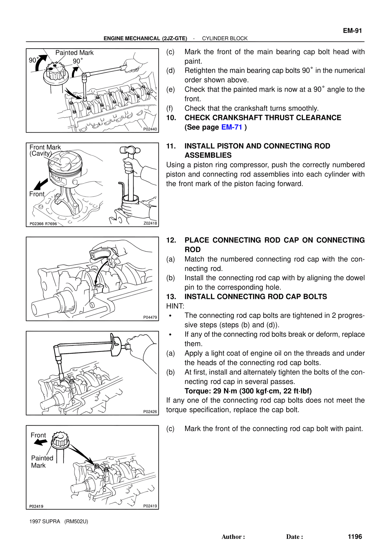
Page text (OCR transcript)
EM-91
ENGINE MECHANICAL (2JZ-GTE) - CYLINDER BLOCK

Painted Mark
90°
90°
P02440

(c) Mark the front of the main bearing cap bolt head with paint.
(d) Retighten the main bearing cap bolts 90° in the numerical order shown above.
(e) Check that the painted mark is now at a 90° angle to the front.
(f) Check that the crankshaft turns smoothly.
10. CHECK CRANKSHAFT THRUST CLEARANCE
(See page EM-71 )

Front Mark
(Cavity)
Front
P02366 R7696
Z02418

11. INSTALL PISTON AND CONNECTING ROD ASSEMBLIES
Using a piston ring compressor, push the correctly numbered piston and connecting rod assemblies into each cylinder with the front mark of the piston facing forward.

P04479

12. PLACE CONNECTING ROD CAP ON CONNECTING ROD
(a) Match the numbered connecting rod cap with the connecting rod.
(b) Install the connecting rod cap with by aligning the dowel pin to the corresponding hole.
13. INSTALL CONNECTING ROD CAP BOLTS
HINT:
• The connecting rod cap bolts are tightened in 2 progressive steps (steps (b) and (d)).
• If any of the connecting rod bolts break or deform, replace them.
(a) Apply a light coat of engine oil on the threads and under the heads of the connecting rod cap bolts.
(b) At first, install and alternately tighten the bolts of the connecting rod cap in several passes.
Torque: 29 N·m (300 kgf·cm, 22 ft·lbf)
If any one of the connecting rod cap bolts does not meet the torque specification, replace the cap bolt.

P02426

Front
Painted
Mark
P02419
P02419

(c) Mark the front of the connecting rod cap bolt with paint.

1997 SUPRA (RM502U)
Author :
Date :
1196