100%
SA–90
SUSPENSION AND AXLE – REAR SUSPENSION
UPPER SUSPENSION ARM REMOVAL
Installation is in the reverse order of removal.
INSTALLATION HINT: After installation, check ABS speed
sensor signal and rear wheel alignment.
(See page BR–62 and SA–9)
1. REMOVE REAR WHEEL
Torque: 103 N·m (1,050 kgf·cm, 76 ft·lbf)
2. REMOVE REAR DRIVE SHAFT
(See page SA–46)
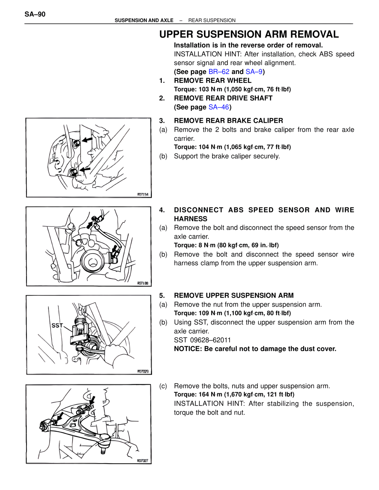
3. REMOVE REAR BRAKE CALIPER
(a) Remove the 2 bolts and brake caliper from the rear axle
carrier.
Torque: 104 N·m (1,065 kgf·cm, 77 ft·lbf)
(b) Support the brake caliper securely.
R07154
4. DISCONNECT ABS SPEED SENSOR AND WIRE
HARNESS
(a) Remove the bolt and disconnect the speed sensor from the
axle carrier.
Torque: 8 N·m (80 kgf·cm, 69 in.·lbf)
(b) Remove the bolt and disconnect the speed sensor wire
harness clamp from the upper suspension arm.
R07188
5. REMOVE UPPER SUSPENSION ARM
(a) Remove the nut from the upper suspension arm.
Torque: 109 N·m (1,100 kgf·cm, 80 ft·lbf)
(b) Using SST, disconnect the upper suspension arm from the
axle carrier.
SST 09628–62011
NOTICE: Be careful not to damage the dust cover.
SST
R07029
(c) Remove the bolts, nuts and upper suspension arm.
Torque: 164 N·m (1,670 kgf·cm, 121 ft·lbf)
INSTALLATION HINT: After stabilizing the suspension,
torque the bolt and nut.
R07027