Page text (OCR transcript)
EG-485
ENGINE — 2JZ-GE ENGINE TROUBLESHOOTING

INSPECTION PROCEDURE

HINT: If terminals TE1 and TE2 are connected with terminal E1, diagnostic trouble code is not output or test
mode is not activated.
Even though terminal TE1 is not connected with terminal E1, the malfunction indicator lamp blinks.
For the above phenomenon, the likely cause is an open or short in the wire harness, or malfunction inside
the ECM.

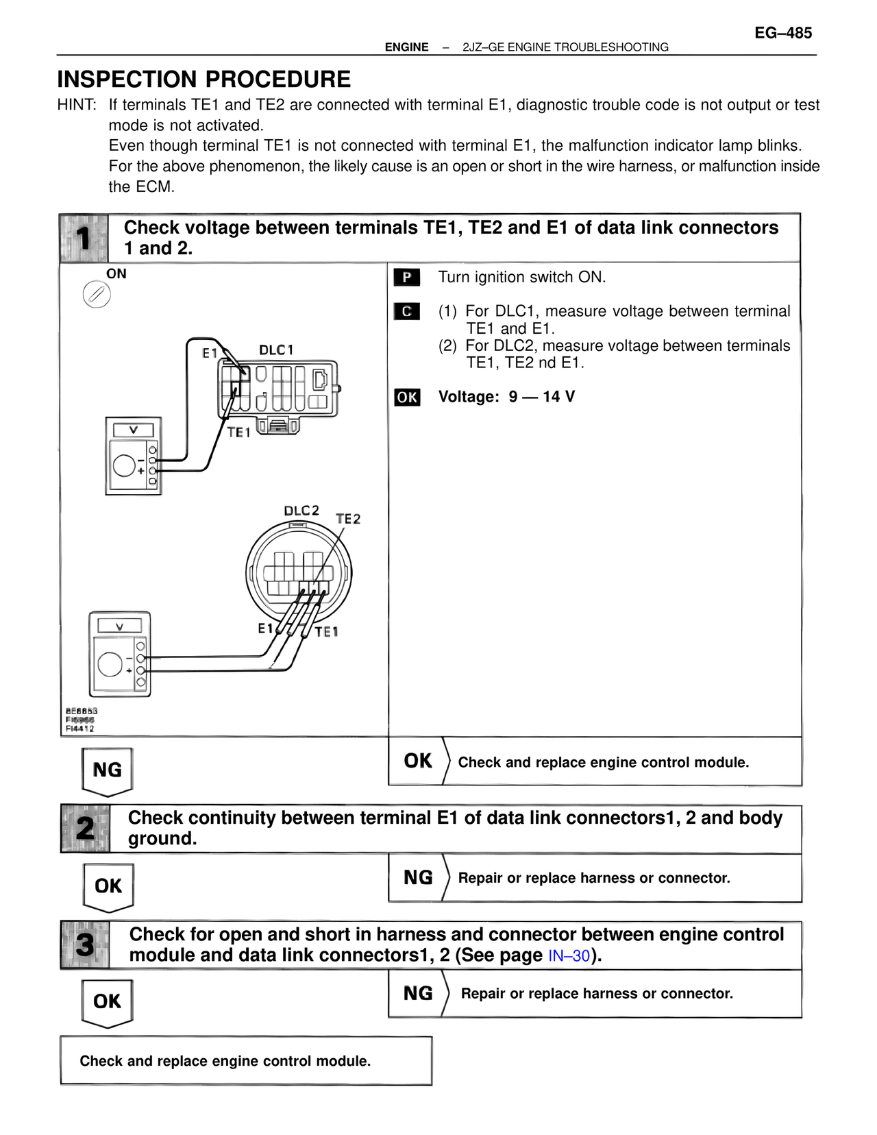
1 Check voltage between terminals TE1, TE2 and E1 of data link connectors
1 and 2.

ON

E1 DLC1

TE1

DLC2 TE2

E1 TE1

BE6853
FI5956
FI4412

P Turn ignition switch ON.

C (1) For DLC1, measure voltage between terminal
TE1 and E1.
(2) For DLC2, measure voltage between terminals
TE1, TE2 nd E1.

OK Voltage: 9 — 14 V

NG

OK Check and replace engine control module.

2 Check continuity between terminal E1 of data link connectors1, 2 and body
ground.

OK

NG Repair or replace harness or connector.

3 Check for open and short in harness and connector between engine control
module and data link connectors1, 2 (See page IN–30).

OK

NG Repair or replace harness or connector.

Check and replace engine control module.