100%
EG–413
ENGINE – 2JZ–GE ENGINE TROUBLESHOOTING
DTC 14 Ignition Signal Circuit
CIRCUIT DESCRIPTION
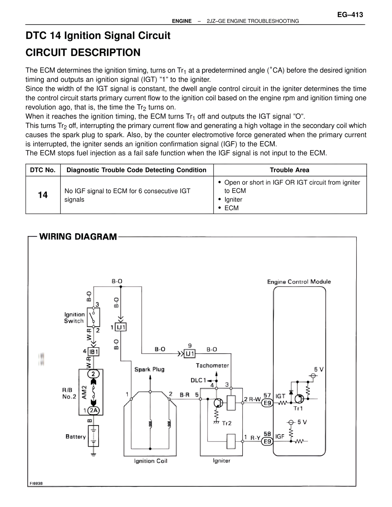
The ECM determines the ignition timing, turns on Tr1 at a predetermined angle (°CA) before the desired ignition timing and outputs an ignition signal (IGT) "1" to the igniter.
Since the width of the IGT signal is constant, the dwell angle control circuit in the igniter determines the time the control circuit starts primary current flow to the ignition coil based on the engine rpm and ignition timing one revolution ago, that is, the time the Tr2 turns on.
When it reaches the ignition timing, the ECM turns Tr1 off and outputs the IGT signal "O".
This turns Tr2 off, interrupting the primary current flow and generating a high voltage in the secondary coil which causes the spark plug to spark. Also, by the counter electromotive force generated when the primary current is interrupted, the igniter sends an ignition confirmation signal (IGF) to the ECM.
The ECM stops fuel injection as a fail safe function when the IGF signal is not input to the ECM.
DTC No. | Diagnostic Trouble Code Detecting Condition | Trouble Area
14 | No IGF signal to ECM for 6 consecutive IGT signals | • Open or short in IGF OR IGT circuit from igniter to ECM
• Igniter
• ECM
WIRING DIAGRAM
B-O
B-O
3
Ignition Switch
2
W-R
4 IB1
B-O
W-R
2
R/B No.2
AM2
1 2A
B
Battery
1 IJ1
B-O
9
B-O >> IJ1
Spark Plug
DLC1 4
1 2 B-R 5
Tr2
Tachometer
3
2 R-W 57
E9
1 R-Y 58
E9
Ignition Coil
Igniter
Engine Control Module
5 V
IGT
Tr1
5 V
IGF
FI6938