Page text (OCR transcript)
INSPECTION PROCEDURE

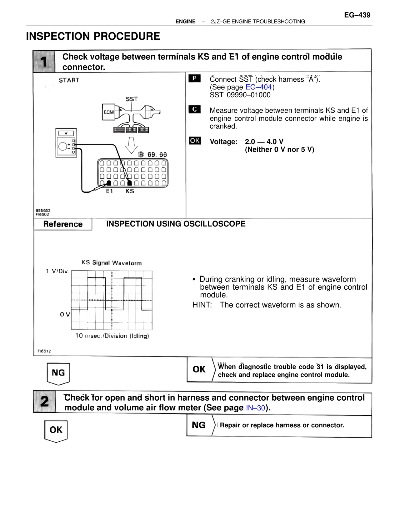
1  Check voltage between terminals KS and E1 of engine control module connector.

START

SST
ECM

B 69, 66

E1    KS

BE6653
FI6502

P  Connect SST (check harness "A").
(See page EG–404)
SST 09990–01000

C  Measure voltage between terminals KS and E1 of engine control module connector while engine is cranked.

OK  Voltage:  2.0 — 4.0 V
(Neither 0 V nor 5 V)

Reference  INSPECTION USING OSCILLOSCOPE

KS Signal Waveform
1 V/Div.

0 V

10 msec./Division (Idling)

FI6512

• During cranking or idling, measure waveform between terminals KS and E1 of engine control module.
HINT:  The correct waveform is as shown.

NG

OK  When diagnostic trouble code 31 is displayed, check and replace engine control module.

2  Check for open and short in harness and connector between engine control module and volume air flow meter (See page IN–30).

OK

NG  Repair or replace harness or connector.