← p.064p.066 →
TGE/Troubleshooting 2JZ-GE — Dtc 42 No.1 Vehicle Speed Sensor Signal Circuit, page 65
65 / 105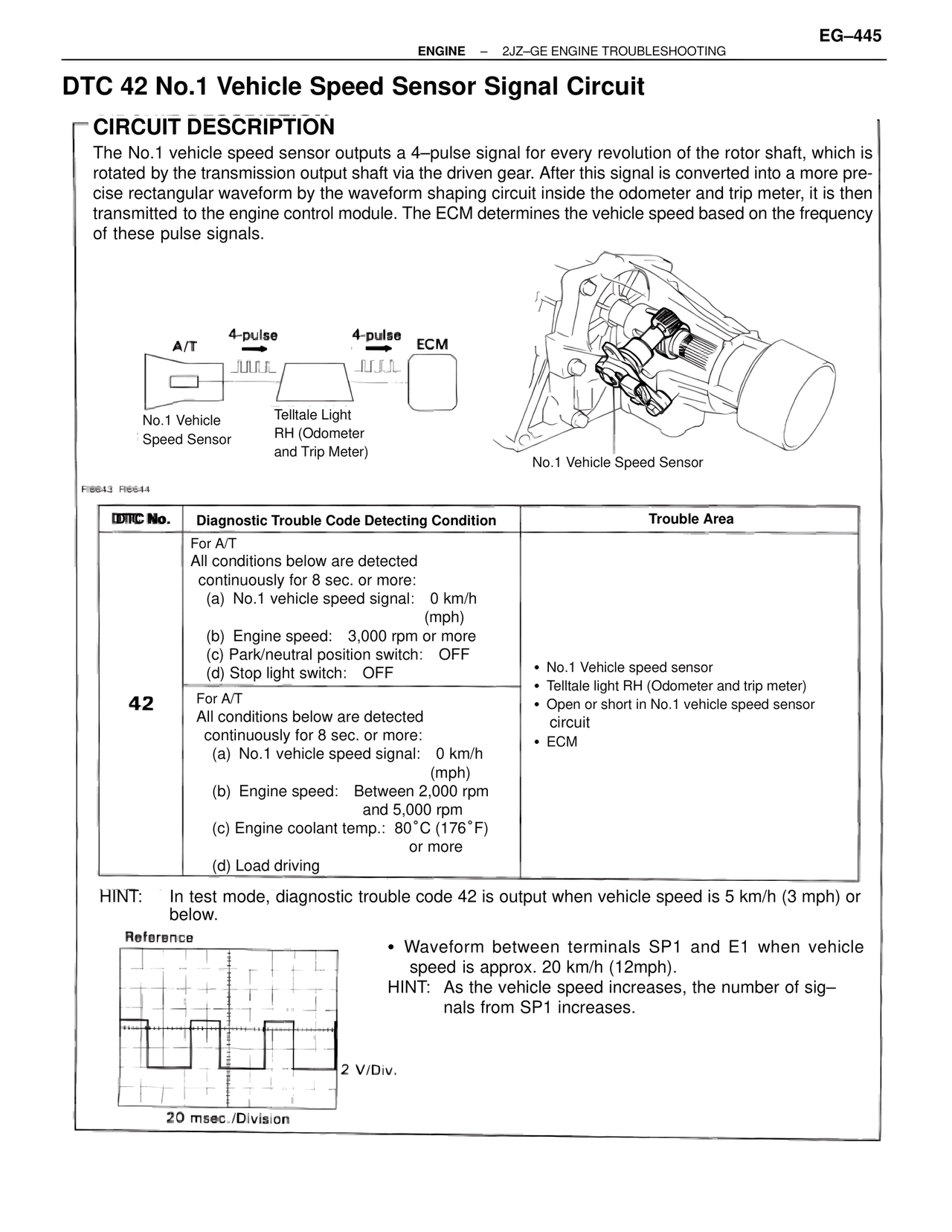
100%
Page text (OCR transcript)
EG-445
ENGINE — 2JZ-GE ENGINE TROUBLESHOOTING

DTC 42 No.1 Vehicle Speed Sensor Signal Circuit

CIRCUIT DESCRIPTION
The No.1 vehicle speed sensor outputs a 4-pulse signal for every revolution of the rotor shaft, which is
rotated by the transmission output shaft via the driven gear. After this signal is converted into a more pre-
cise rectangular waveform by the waveform shaping circuit inside the odometer and trip meter, it is then
transmitted to the engine control module. The ECM determines the vehicle speed based on the frequency
of these pulse signals.

A/T    4-pulse    4-pulse    ECM
No.1 Vehicle
Speed Sensor
Telltale Light
RH (Odometer
and Trip Meter)

No.1 Vehicle Speed Sensor

FI6643 FI6644

DTC No.    Diagnostic Trouble Code Detecting Condition    Trouble Area

42
For A/T
All conditions below are detected
continuously for 8 sec. or more:
(a) No.1 vehicle speed signal: 0 km/h
(mph)
(b) Engine speed: 3,000 rpm or more
(c) Park/neutral position switch: OFF
(d) Stop light switch: OFF

For A/T
All conditions below are detected
continuously for 8 sec. or more:
(a) No.1 vehicle speed signal: 0 km/h
(mph)
(b) Engine speed: Between 2,000 rpm
and 5,000 rpm
(c) Engine coolant temp.: 80°C (176°F)
or more
(d) Load driving

• No.1 Vehicle speed sensor
• Telltale light RH (Odometer and trip meter)
• Open or short in No.1 vehicle speed sensor
circuit
• ECM

HINT: In test mode, diagnostic trouble code 42 is output when vehicle speed is 5 km/h (3 mph) or
below.

Reference

2 V/Div.

20 msec./Division

• Waveform between terminals SP1 and E1 when vehicle
speed is approx. 20 km/h (12mph).
HINT: As the vehicle speed increases, the number of sig-
nals from SP1 increases.